SICK FLOWSIC500 Operating Instructions Manual
Ultrasonic gas flow meter with optional volume conversion
Hide thumbs
Also See for FLOWSIC500:
- Operating instructions manual (138 pages) ,
- Operating instructions manual (158 pages) ,
- Operating instructions manual (114 pages)

Related Manuals for SICK FLOWSIC500


Summary of Contents for SICK FLOWSIC500
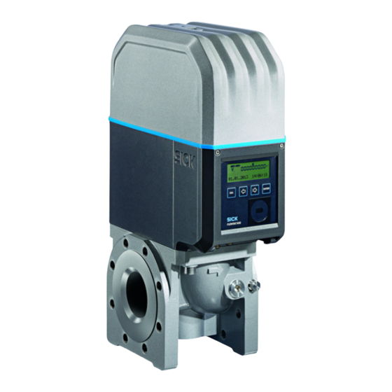
- Page 1 Title Page O P E R A T I N G I N S T R U C T I O N S FLOWSIC500 Ultrasonic Gas Flow Meter with Optional Volume Conversion Installation Operation Maintenance...
- Page 2 Volume conversion as function of the temperature © SICK Engineering GmbH. All rights reserved. and a fixed pressure value and with consideration of the compression factor FLOWSIC500 · Operating Instructions · 8025733/1GMJ/V 4-2/2022-07 · © SICK Engineering GmbH...
- Page 3 Risk or hazardous situation which could result in severe personal injury or death. CAUTION Hazard or unsafe practice which could result in less severe or minor injuries. NOTICE Hazards which could result in property damage FLOWSIC500 · Operating Instructions · 8025733/1GMJ/V 4-2/2022-07 · © SICK Engineering GmbH...
-
Page 4: Table Of Contents
............36 FLOWSIC500 · Operating Instructions · 8025733/1GMJ/V 4-2/2022-07 · © SICK Engineering GmbH... - Page 5 Function check after commissioning ........78 FLOWSIC500 · Operating Instructions · 8025733/1GMJ/V 4-2/2022-07 · © SICK Engineering GmbH...
- Page 6 FLOWSIC500 menu ........
- Page 7 ATEX/IECEx ............167 FLOWSIC500 · Operating Instructions · 8025733/1GMJ/V 4-2/2022-07 · © SICK Engineering GmbH...
- Page 8 Cont ents FLOWSIC500 · Operating Instructions · 8025733/1GMJ/V 4-2/2022-07 · © SICK Engineering GmbH...
-
Page 9: Important Information
Important information FLOWSIC500 Important information Main hazards About this document Intended use Responsibility of user Additional documentation/information Information on cybersecruity threats FLOWSIC500 · Operating Instructions · 8025733/1GMJ/V 4-2/2022-07 · © SICK Engineering GmbH... -
Page 10: Main Hazards
– Device components – Installation – Operation of the FLOWSIC500. It contains the main safety information for safe operation of the FLOWSIC500. Application area of the document This document is valid for FLOWSIC500 with firmware version 2.15.00 and higher. FLOWSIC500 with Ex approval acc. CSA... -
Page 11: Intended Use
1 .3 Purpose of the device 1.3.1 The FLOWSIC500 serves for measuring the gas volume, volume flow rate and gas velocity of natural gas in pipelines. The FLOWSIC500 with optional volume conversion serves for measuring the gas volume and converting the gas volume measured to base conditions as well as registering data on totalizer levels, maximums and other data. -
Page 12: Operation In Potentially Explosive Atmospheres
Refer to the type plate for the configuration of your FLOWSIC500. ▸ Check the FLOWSIC500 is suitably equipped for your application (e.g., gas conditions). WARNING: Hazard through material fatigue The FLOWSIC500 has been designed for use under mainly static loads. -
Page 13: Cleaning
The manufacturer bears no responsibility for any other use. ▸ Do not carry out any work or repairs on the FLOWSIC500 not described in this manual. ▸ Do not remove, add or change any components in or on the FLOWSIC500 unless such changes are officially allowed and specified by the manufacturer. -
Page 14: Additional Documentation/Information
● Printed Parameter report ● Product CD: – Operating Instructions – FLOWgate operating software – FLOWgate Software Manual – Certificates – Instructions/information for accessories – Calibration instructions – Modbus specification FLOWSIC500 · Operating Instructions · 8025733/1GMJ/V 4-2/2022-07 · © SICK Engineering GmbH... -
Page 15: Information On Cybersecruity Threats
Visit www.sick.com/psirt for more information, such as: ● General information on cybersecurity ● Contact option for reporting vulnerabilities ● Information on known vulnerabilities (Security Advisories) FLOWSIC500 · Operating Instructions · 8025733/1GMJ/V 4-2/2022-07 · © SICK Engineering GmbH... - Page 16 Important information FLOWSIC500 · Operating Instructions · 8025733/1GMJ/V 4-2/2022-07 · © SICK Engineering GmbH...
-
Page 17: Product Description
Product description FLOWSIC500 Product description Measuring principle System components FLOWgate operating software Interfaces Totalizers Data processing in Device option Parameter protection Sealing PowerIn Technology FLOWSIC500 · Operating Instructions · 8025733/1GMJ/V 4-2/2022-07 · © SICK Engineering GmbH... -
Page 18: Measuring Principle
The FLOWSIC500 calculates the volume flow rate internally from the gas velocity and the diameter of the measuring section of the gas flow meter. -
Page 19: System Components
Depending on the version, the adapter is designed for assembly on line flanges PN16 in accordance with DIN EN1092-1, CL150 in accordance with ASME B16.5, or 1.6MPa in accordance with GOST 12815-80. Fitting lengths available: → p. 155, §9.6. FLOWSIC500 · Operating Instructions · 8025733/1GMJ/V 4-2/2022-07 · © SICK Engineering GmbH... -
Page 20: Gas Flow Meter
The product variant with volume conversion and integrated pressure and temperature sensors also has the calibrated pressure sensor and calibrated temperature sensor fitted in the gas flow meter. Meter sizes 2.2.3 Available meter sizes → p. 155, §9.6. FLOWSIC500 · Operating Instructions · 8025733/1GMJ/V 4-2/2022-07 · © SICK Engineering GmbH... -
Page 21: Flowgate Tm Operating Software
● Field setup wizard ● Parameter modification ● Logbook and archive management ● Calibration ● Diagnostics data ● Service actions ● Session browser Software platform FLOWgate – FLOWSIC500 “Overview” Fig. 4 FLOWSIC500 · Operating Instructions · 8025733/1GMJ/V 4-2/2022-07 · © SICK Engineering GmbH... -
Page 22: System Requirements
User can be deactivated Read parameters and measured values Read data archive Change parameters not custody relevant Change custody relevant parameters - User management Calibration mode Configuration mode Test digital outputs FLOWSIC500 · Operating Instructions · 8025733/1GMJ/V 4-2/2022-07 · © SICK Engineering GmbH... -
Page 23: Interfaces
● Details on standard interface configurations available → p. 51, §3.4.6. Pulse and status outputs 2.4.1 FLOWSIC500 has 4 digital switching outputs. Digital switching outputs DO_0, DO_2 and DO_3 are electrically isolated according to EN 60947-5-6. Alternatively, digital switching outputs DO_2 and DO_3 can also be configured as Open Collector. -
Page 24: Optical Data Interface
Device status and totalizers used 2.5.1 Various volume totalizers are fitted on the FLOWSIC500 depending on the configuration. Meter V is used in the configuration as gas flow meter. If the gas flow meter has a malfunction, the measured volume is also recorded in the error volume counter errV. -
Page 25: Data Processing In
All events with timestamp, user logged on and totalizer level, max. number of entries: 1000 When the Event logbook is 90% full, the FLOWSIC500 changes to device status “Warning”, warning W-2001 is shown on the display. When the Event logbook is full, the FLOWSIC500 changes to device status “Malfunction”, error E-3001 is shown on the display (→... -
Page 26: Archives
The FLOWSIC500 checks the permissible entry limits of the parameters for the selected calculation method. If one of the entry values is outside the limit values, the FLOWSIC500 switches to malfunction state and uses the fixed value of the compressibility factor for calculation of the basis volume. - Page 27 It is recommended to install a three-way test valve that separates the pressure sensor from the measurement pressure and provides a test connection to test the pressure sensor. → Fig. 5 shows a FLOWSIC500 with external sensors and test valve BDA04 for gas tempera- tures to -25°C.
- Page 28 1 Pressure sensor 2 Test valve BDA04 3 Temperature sensor A three-way test valve (→ Fig. 6) that is fitted next to the FLOWSIC500 is used for gas temperatures to -40°C. Fig. 6 Three-way test valve with p-sensor and Minimess coupling 1 Pipe screw fitting 1/4“...
-
Page 29: Load Recording Device With Maximum Load Display
If the feature "Load recording device with maximum load display" is activated, the FLOWSIC500 checks if the measuring period or the daily period is still valid when ending the measuring period or the daily period. If the period is valid, the consumption of this period is used for updating the daily and monthly extreme values. -
Page 30: Extension Measurement Capability Up To 30% Hydrogen
For a meter in the field, activation of the feature via a SICK license is only possible in com- pliance with national regulations. -
Page 31: Parameter Protection
(for gas flow meters) or Vb (for gas flow meters with device option volume conversion) and the logged on user. The Metrology logbook can have a maximum of 100 entries. The FLOWSIC500 switches to status “Warning” when the Metrology logbook is full. - Page 32 T Adjust factor Factor for temperature sensor adjustment Measuring period Period for billing archive Gas hour Billing hour for the day archive Gas day Billing day for month archive FLOWSIC500 · Operating Instructions · 8025733/1GMJ/V 4-2/2022-07 · © SICK Engineering GmbH...
-
Page 33: Gas Composition Logbook
Heptane proportion in gas n-octane Octane proportion in gas n-nonane Nonane proportion in gas n-decane Decane proportion in gas Helium Helium proportion in gas Argon Argon proportion in gas FLOWSIC500 · Operating Instructions · 8025733/1GMJ/V 4-2/2022-07 · © SICK Engineering GmbH... -
Page 34: Sealing
Sealing 2 . 9 The FLOWSIC500 is secured at the factory with a seal on the cover. Gas flow meter and adapter can be secured at the joint by a user seal (adhesive label) glued with approximately equal spread on gas flow meter and adapter. - Page 35 Fig. 10 Seal on the temperature sensor (example) 1 Temperature sensor 2 Locknut 3 Wire seal FLOWSIC500 · Operating Instructions · 8025733/1GMJ/V 4-2/2022-07 · © SICK Engineering GmbH...
-
Page 36: Powerin Technology Tm
● Self-sufficient power configuration: 2 internal longlife battery packs (typical service life: At least 5 years). The second battery pack is activated automatically when the first pack is empty and a message displayed (→ p. 80, §5.2). FLOWSIC500 · Operating Instructions · 8025733/1GMJ/V 4-2/2022-07 · © SICK Engineering GmbH... -
Page 37: Installation
Installation FLOWSIC500 Installation Hazards during installation General information Mechanical installation Electrical installation Installing the external pressure and temperature sensors Fitting a display protector (option) FLOWSIC500 · Operating Instructions · 8025733/1GMJ/V 4-2/2022-07 · © SICK Engineering GmbH... -
Page 38: Hazards During Installation
Inspect for transport damage when unpacking the device. ▸ Document any damage found and report this to the manufacturer. NOTICE: Do not put the FLOWSIC500 into operation if you notice any damage! ▸ Check the scope of delivery for completeness. The standard scope of delivery comprises: ●... -
Page 39: Transport
DIN EN 1591-4. The FLOWSIC500 normally does not need straight inlet and outlet sections and can be fitted directly after bends in the pipe. NOTICE: Installation requirements ▸... -
Page 40: Choosing Flanges, Gaskets And Other Components
(narrow (UNC series) length 4.0"- ASME series) Ø 3/4" - Ø 3/4" - B18.31.2, ANSI B18.22.1, ANSI B18.2.2, ASTM A193 Grade grade 8 stainless ASTM A194 Grade steel FLOWSIC500 · Operating Instructions · 8025733/1GMJ/V 4-2/2022-07 · © SICK Engineering GmbH... - Page 41 Class 150 / ASME B16.5 2"/ Cl150 3"/ Cl150 novapress® FLEXIBLE/815 4"/ Cl150 6"/ Cl150 [1] Da = outer diameter, Di = inner diameter, S = thickness, → Fig. 12 FLOWSIC500 · Operating Instructions · 8025733/1GMJ/V 4-2/2022-07 · © SICK Engineering GmbH...
- Page 42 PN16 / EN1092-1 DN50/ PN16 DN80/ PN16 novapress® FLEXIBLE/815 DN100/ PN16 DN150/ PN16 [1] Da = outer diameter, Di = inner diameter, S = thickness, → Fig. 12 FLOWSIC500 · Operating Instructions · 8025733/1GMJ/V 4-2/2022-07 · © SICK Engineering GmbH...
-
Page 43: Fitting In The Pipeline
3.3.3 NOTICE: The lifting lug is designed for transporting the measuring device only. Do not lift or transport the FLOWSIC500 with additional loads using this lug. ▸ The FLOWSIC500 must not swing or tilt on the hoisting equipment during transport. - Page 44 [mm] [in] [mm] [in] [mm] [in] DN50/2" 11,81 13,39 7,87 DN80/3" 18,11 20,08 9,84 DN100/4" 20,47 22,44 12,6 DN150/6" 20,47 22,44 12,6 FLOWSIC500 · Operating Instructions · 8025733/1GMJ/V 4-2/2022-07 · © SICK Engineering GmbH...
- Page 45 3.3.3.3 1 Select suitable bolts. Recommended bolts → Table 8. 2 Use the hoisting equipment to position the FLOWSIC500 in the desired location in the pipeline. Lay the pipelines without tension to the device to be installed! 3 Insert and align the gaskets.
-
Page 46: Electrical Installation
The documentation for zone categorization in accordance with IEC60079-10 must be available ▸ The FLOWSIC500 must have been checked for suitability for the actual installation location and the Ex marking on the device must match the requirements. ▸ After installation and before initial commissioning, the complete equipment and the system must be inspected in compliance with IEC 60079-17. - Page 47 – Air with normal oxygen content, normally 21 percent by volume The ambient temperature must be within the range specified on the type plate. The gas flow meter becomes part of the pipeline as soon as the FLOWSIC500 is installed in the pipeline.
-
Page 48: Criteria For Electrical Connection
Opening and closing the electronics cover 3.4.3 The Ex i terminal compartment of the FLOWSIC500 can be accessed after the electronics cover has been opened. The cover may also be opened in the hazardous area when under voltage. However, safe separation between the various intrinsically safe power circuits must not be breached. -
Page 49: Rotating The Control Unit
5 Rotate the display in the desired direction and reposition. 6 Tighten the display screws evenly. Tightening torque: 1.0 Nm (9 lbf in) 7 Close the electronics cover again. FLOWSIC500 · Operating Instructions · 8025733/1GMJ/V 4-2/2022-07 · © SICK Engineering GmbH... -
Page 50: Electrical Connections
→ p. 51, §3.4.6. The respective configuration is printed on the type plate (→ p. 54). The external power supply need not be connected when the FLOWSIC500 is operated with internal batteries. FLOWSIC500 · Operating Instructions · 8025733/1GMJ/V 4-2/2022-07 · © SICK Engineering GmbH... -
Page 51: Pin Assignment Of Plug-In Connectors
OC (Open Collector)*: 100 Hz at 120% Q Max. 16 V DO_2+ Rated current 20 mA or NAMUR: Rated input voltage 8.2 V = 3.4 mA = 0.7 mA FLOWSIC500 · Operating Instructions · 8025733/1GMJ/V 4-2/2022-07 · © SICK Engineering GmbH... - Page 52 Rated input voltage IIB: C = 1.35 µF = 4 … 16 V = 0.03 mH PWR- Low voltage version: Rated input voltage Data B = 2.7 ... 5 V FLOWSIC500 · Operating Instructions · 8025733/1GMJ/V 4-2/2022-07 · © SICK Engineering GmbH...
- Page 53 Standard version: IIC: C = 0.22 µF Data A Rated input voltage IIB: C = 1.35 µF = 4 … 16 V = 0.03 mH PWR- Data B FLOWSIC500 · Operating Instructions · 8025733/1GMJ/V 4-2/2022-07 · © SICK Engineering GmbH...
-
Page 54: Do Configuration Switch (Open Collector - Namur)
“ON”: 0 U “On”: “On”: = 3.4 mA “ON”: 0 U 2V; 2mA I 20mA “OFF”:I “OFF”: “OFF”: = 0.7 mA 0.2 mA (leakage flow) “OFF”: I temperature fuse FLOWSIC500 · Operating Instructions · 8025733/1GMJ/V 4-2/2022-07 · © SICK Engineering GmbH... -
Page 55: Cable Specifications
Installation Cable specifications 3.4.8 When the plugs available from SICK are used, a shielded control cable with 4x0.25 mm cross-section, with PVC insulation and approx. 5 mm outer diameter is required. WARNING: Requirements on cables and installation ▸ Pay attention to the requirements in EN 60079-14 when selecting the cables and during installation! ▸... -
Page 56: Operation With External Power Supply
2 Connect the backup battery (Part No. 2065928) to connection BAT2 in the terminal compartment (→ Fig. 24). 3 Close the electronics cover again. Fig. 24 Connected backup batteries FLOWSIC500 · Operating Instructions · 8025733/1GMJ/V 4-2/2022-07 · © SICK Engineering GmbH... -
Page 57: Battery Operation
Only connect the battery packs to the connections marked for this purpose in the terminal compartment of the FLOWSIC500. ▸ Modifying the electrical connection parts is not allowed. FLOWSIC500 · Operating Instructions · 8025733/1GMJ/V 4-2/2022-07 · © SICK Engineering GmbH... - Page 58 BAT1 and BAT2 in the terminal compartment. The FLOWSIC500 is initialized. Fig. 25 Connected battery packs 3 Close the electronics cover again. 4 Set the date and time (→ p. 68, §4.2). FLOWSIC500 · Operating Instructions · 8025733/1GMJ/V 4-2/2022-07 · © SICK Engineering GmbH...
-
Page 59: Installing The External Pressure And Temperature Sensors
3.5.1 Fit the plug-in connector cover before installing the sensors. 1 Guide the sensor plugs through the openings in the plug-in connector cover. Fig. 27 Plug-in connector cover FLOWSIC500 · Operating Instructions · 8025733/1GMJ/V 4-2/2022-07 · © SICK Engineering GmbH... - Page 60 3 Push the plug-in connector cover over the plugs and fasten with both capstan screws. Fig. 29 Fastening the plug-in connector cover 1 Capstan screw 2 Plug-in connector cover FLOWSIC500 · Operating Instructions · 8025733/1GMJ/V 4-2/2022-07 · © SICK Engineering GmbH...
-
Page 61: Installing The Pressure Sensor
NOTICE: Fitting information It is recommended to connect the pressure sensor with the three-way test valve or with the FLOWSIC500 so that there is a downward slope from the pressure sensor to the connection point and from the three-way test valve to the FLOWSIC500. - Page 62 2 Test valve BDA04 3 FLOWSIC500 connection (G 1/4“ male thread) Table 20 Test valve BDA04 positions Measuring Pressure sensor position FLOWSIC500 Test pressure Test position Pressure sensor FLOWSIC500 FLOWSIC500 · Operating Instructions · 8025733/1GMJ/V 4-2/2022-07 · © SICK Engineering GmbH...
- Page 63 Here, a conventional three-way test valve is used. Install the three-way test valve with pressure sensor fitted at a suitable location next to the FLOWSIC500. A pressure line serves to connect the pressure measuring connection of the FLOWSIC500 to the three-way test valve.
- Page 64 2 When the meter body has an NPT 1/4“ thread, first screw in the adapter (Part No. 2075562). 3 Fit the pressure sensor. Fig. 34 Installation without three-way test valve 1 Pressure sensor, connection thread G 1/4“ FLOWSIC500 · Operating Instructions · 8025733/1GMJ/V 4-2/2022-07 · © SICK Engineering GmbH...
-
Page 65: Installing The Temperature Sensor
Fitting a display protector (option) 3 .6 Display protector (Part No. 2085547) is available as an option for protection of the display from UV light. Fig. 36 Display protection FLOWSIC500 · Operating Instructions · 8025733/1GMJ/V 4-2/2022-07 · © SICK Engineering GmbH... - Page 66 2 Instead, mount the delivered screws with a SW 6 jaw wrench. 3 Mount the display cover with the pre- mounted screws (captive) using an Allen key SW 2.5. FLOWSIC500 · Operating Instructions · 8025733/1GMJ/V 4-2/2022-07 · © SICK Engineering GmbH...
-
Page 67: Commissioning
Commissioning FLOWSIC500 Commissioning General information Commissioning on the display Commissioning with the FLOWgate operating software FLOWSIC500 · Operating Instructions · 8025733/1GMJ/V 4-2/2022-07 · © SICK Engineering GmbH... -
Page 68: General Information
The alarm limits are set in the factory to the measuring range of the selected sensor ▸ Terminate configuration mode (→ p. 97, §5.2.9). ▸ Check the device status (→ p. 70, §4.2.4). FLOWSIC500 · Operating Instructions · 8025733/1GMJ/V 4-2/2022-07 · © SICK Engineering GmbH... -
Page 69: Setting The Date And Time
Setting the date and time 4.2.2 Date and time must be set after the power supply has been connected. The FLOWSIC500 displays error E-3007 (“Time invalid”) until the time has been set. Detailed information on operating using the display and on menu navigation →... -
Page 70: Checking The Device Status
– Contact SICK Customer Service for any malfunctions you cannot clear yourself (→ p. 102, §6.1, “Contacting Customer Service”). 4 The event overview can be reset when all warnings and errors have been cleared (→ p. 98, §5.2.12). FLOWSIC500 · Operating Instructions · 8025733/1GMJ/V 4-2/2022-07 · © SICK Engineering GmbH... -
Page 71: Commissioning With The Flowgate Tm Operating Software
A data connection can be established with the device using the optical data interface and the infrared/USB adapter HIE-04 (Part No. 6050502). This interface serves to configure the FLOWSIC500. The infrared/USB adapter has a USB 2.0 interface. This interface provides the connection to the PC and transfers the FLOWSIC500 data. -
Page 72: Field Setup Wizard
Up to three users and three authorized users can be activated. “Authorized User 1” and “User 1” are always activated, For access rights for single user levels, see → p. 22, §2.3.3. Fig. 38 Example FLOWSIC500 · Operating Instructions · 8025733/1GMJ/V 4-2/2022-07 · © SICK Engineering GmbH... - Page 73 Commissioning Warnings 4.3.2.3 The “Warnings” area serves to set the limit values outside of which the FLOWSIC500 is to output warnings (flow rate) or errors (pressure and temperature). Limit values can be set for: ● Flow rate ● Pressure ● Temperature ●...
- Page 74 ● Flow rate – Enter the desired test flow rate and start the test. ● Digital output – Select the desired digital output. – Push the slider to “On”. FLOWSIC500 · Operating Instructions · 8025733/1GMJ/V 4-2/2022-07 · © SICK Engineering GmbH...
- Page 75 Commissioning Volume conversion (only for device option volume conversion) 4.3.2.5 For a detailed description of the single parameters, see the FLOWSIC500 menu description, p. 91, §5.2.6.5. ▸ Determine the reference values. ▸ Enter the specifications for gas characteristics. ▸ Select the algorithm and parameters for calculating the compressibility factor.
-
Page 76: Activate And Configure The Daylight Saving Time
Setting the time period for the daylight saving time 6 Then set the end of the daylight saving time. 7 Click “Write to device” to write the daylight saving time to the FLOWSIC500. 8 Enter further time periods when desired. Daylight saving time start and end can be configured for up to 10 years in advance. -
Page 77: Configure The Power Management
Commissioning Configure the power management 4.3.4 Select the type of power supply corresponding to the configuration of the FLOWSIC500: ● Dynamic Mode (External + Backup): Measuring rate: 4 Hz ● Battery Mode (2 x Battery): Measuring rate: 1 Hz, to maximize the battery service life ●... -
Page 78: Function Check After Commissioning
▸ Click on the symbol in the Status bar when warnings or errors exist. The current Status overview opens and shows details and information on how to proceed. FLOWSIC500 · Operating Instructions · 8025733/1GMJ/V 4-2/2022-07 · © SICK Engineering GmbH... -
Page 79: Operation
Operation FLOWSIC500 Operation Control unit Operating using the display FLOWSIC500 · Operating Instructions · 8025733/1GMJ/V 4-2/2022-07 · © SICK Engineering GmbH... -
Page 80: Control Unit
Increments or decrements a parameter Toggles between single menu entries by 1, toggles between several selection on one level options. ENTER Calls a submenu, starts edit mode. Confirms an input. FLOWSIC500 · Operating Instructions · 8025733/1GMJ/V 4-2/2022-07 · © SICK Engineering GmbH... -
Page 81: Display In The Symbol Bar
● The last segment of the battery symbol starts to blink when the battery fill level drops below 10%. ● When the battery is completely empty, the empty battery symbol blinks and the FLOWSIC500 has switched to the second battery. FLOWSIC500 · Operating Instructions · 8025733/1GMJ/V 4-2/2022-07 · © SICK Engineering GmbH... -
Page 82: Main Screen (Without Device Option Volume Conversion)
→ “Resetting the event summary” (p. 98). NOTICE: A parameter with Malfunction status is shown on the display by a blinking exclamation mark after the parameter (e. g. Q!). FLOWSIC500 · Operating Instructions · 8025733/1GMJ/V 4-2/2022-07 · © SICK Engineering GmbH... - Page 83 Main display: Event Summary ○ ○ ○ ○ List of stored events ○ ○ ○ ○ Main display: Last Event Reset ○ ○ ● ● → p. 98, §5.2.12 FLOWSIC500 · Operating Instructions · 8025733/1GMJ/V 4-2/2022-07 · © SICK Engineering GmbH...
-
Page 84: Main Display (With Device Option Volume Conversion)
Q = Volume flow at measurement conditions Qb = Volume flow at base conditions 0.000 m3/h 0.000 m3/h SOS = Sound velocity currently measured VOG = Gas velocity currently measured 430.00 m/s 0.000 m/s FLOWSIC500 · Operating Instructions · 8025733/1GMJ/V 4-2/2022-07 · © SICK Engineering GmbH... - Page 85 → “Resetting the event summary” (p. 98). NOTICE: A parameter with Malfunction status is shown on the display by a blinking exclamation mark after the parameter (e. g. Q!). FLOWSIC500 · Operating Instructions · 8025733/1GMJ/V 4-2/2022-07 · © SICK Engineering GmbH...
- Page 86 ○ ● ● Heating value ○ ○ ● ● Heating value unit ○ ○ ● ● FLOWSIC500 menu: Pressure parameters ○ ○ ○ ○ → p. 92, §5.2.6.6 FLOWSIC500 · Operating Instructions · 8025733/1GMJ/V 4-2/2022-07 · © SICK Engineering GmbH...
- Page 87 Main display: Event Summary ○ ○ ○ ○ List of stored events ○ ○ ○ ○ Main display: Last Event Reset ○ ○ ● ● → p. 98, §5.2.12 FLOWSIC500 · Operating Instructions · 8025733/1GMJ/V 4-2/2022-07 · © SICK Engineering GmbH...
-
Page 88: Configuration Of Main Display
→ “Changing the user level” (p. 97) Logged in as: User (1) ● User (2)* ● User (3)* ● Authorized user (1) ● Authorized user (2)* ● Authorized user (3)* ● * when activated FLOWSIC500 · Operating Instructions · 8025733/1GMJ/V 4-2/2022-07 · © SICK Engineering GmbH... - Page 89 Device time → “Commissioning on the display” (p. 68) Timezone Time zone set on device Language Language for displays Available: English, German, Russian → “Setting the language” (p. 97) FLOWSIC500 · Operating Instructions · 8025733/1GMJ/V 4-2/2022-07 · © SICK Engineering GmbH...
- Page 90 Velocity of gas VOG VOG Speed of sound SOS SOS Compressibility Conversion factor Compression factor (measurement) Z Compression factor (base) LCD test Display test → “Testing the display” (p. 99) FLOWSIC500 · Operating Instructions · 8025733/1GMJ/V 4-2/2022-07 · © SICK Engineering GmbH...
- Page 91 Relative density Relative density, relation between gas density and air density under reference conditions - proportion in gas [mol%] - proportion in gas [mol%] - proportion in gas [mol%] FLOWSIC500 · Operating Instructions · 8025733/1GMJ/V 4-2/2022-07 · © SICK Engineering GmbH...
- Page 92 The detailed view shows the event type, a short text and the timestamp. Parameter logbook Number of entries currently stored/max. number Metrology logbook Number of entries currently stored/max. number Gas composition logbook Number of entries currently stored/max. number FLOWSIC500 · Operating Instructions · 8025733/1GMJ/V 4-2/2022-07 · © SICK Engineering GmbH...
- Page 93 Average pressure and TMPØ temperature (flow-weighted) KMPØ Average compressibility and CMPØ conversion factor (flow-weighted) SOSMPØ Average speed of sound, Flowtime Flowtime (time with Q > LowFlowCutOff) FLOWSIC500 · Operating Instructions · 8025733/1GMJ/V 4-2/2022-07 · © SICK Engineering GmbH...
- Page 94 Minimum temperature during day TDy↓ Date/Time Timestamp of minimum temperature during day KDyØ Average compressibility and CDyØ conversion factor (flow-weighted) during day SOSDyØ Average speed of sound during day FLOWSIC500 · Operating Instructions · 8025733/1GMJ/V 4-2/2022-07 · © SICK Engineering GmbH...
- Page 95 Timestamp of maximum temperature occurred during month TMo↓ Minimum temperature occurred during month TMo↓ Date/Time Timestamp of minimum temperature occurred during month KMoØ Average compressibility and CMoØ conversion factor (flow-weighted) during month FLOWSIC500 · Operating Instructions · 8025733/1GMJ/V 4-2/2022-07 · © SICK Engineering GmbH...
- Page 96 VmDy↑ Maximum progress of V in a day of the previous month VmDy↑ Date/Time Timestamp of maximum progress of V in a day of the previous month FLOWSIC500 · Operating Instructions · 8025733/1GMJ/V 4-2/2022-07 · © SICK Engineering GmbH...
-
Page 97: Changing The User Level
5 Confirm with ENTER. The display texts are now shown in the selected language. Changing the device mode 5.2.9 On the FLOWSIC500, the device modes Configuration and Calibration can be activated independently from each other. Starting and terminating configuration mode 5.2.9.1 Start configuration mode 1 Switch to the “Device mode”... -
Page 98: Changing Parameters
In calibration mode, message “CALIBRATION MODE” blinks on the main display with the meter factor now effective for the calibration (set at the factory). The FLOWSIC500 outputs test pulses with a maximum possible frequency of 2 kHz at 120% Q .on digital switching output DO_1 (→... -
Page 99: Confirming Battery Replacement
If there is no exact match, the archive entry will be determined for which the difference to the searched value is the smallest. If there is no matching entry, the system returns to the last archive entry displayed. FLOWSIC500 · Operating Instructions · 8025733/1GMJ/V 4-2/2022-07 · © SICK Engineering GmbH... - Page 100 Operation FLOWSIC500 · Operating Instructions · 8025733/1GMJ/V 4-2/2022-07 · © SICK Engineering GmbH...
-
Page 101: Clearing Malfunctions
Clearing malfunctions FLOWSIC500 Clearing malfunctions Contacting Customer Service Status messages Additional messages in the Event logbook Starting a diagnostic session FLOWSIC500 · Operating Instructions · 8025733/1GMJ/V 4-2/2022-07 · © SICK Engineering GmbH... -
Page 102: Contacting Customer Service
→ p. 111, §7.3.2 “Changing the battery packs” W-2018 External power supply failure. Check the connection and function of the external power supply. → p. 56, §3.4.9 “Operation with external power supply”. FLOWSIC500 · Operating Instructions · 8025733/1GMJ/V 4-2/2022-07 · © SICK Engineering GmbH... - Page 103 E-3022 = Gas pressure is above the alarm limit E-3021 Check the set alarm limit values. E-3022 → p. 92, §5.2.6.7 “Temperature parameters” E-3023 Time is inaccurate. Check time synchronisation. FLOWSIC500 · Operating Instructions · 8025733/1GMJ/V 4-2/2022-07 · © SICK Engineering GmbH...
-
Page 104: Additional Messages In The Event Logbook
Additional messages in the Event logbook 6 . 3 The FLOWSIC500 saves all status messages (→ p. 102, §6.2) as well as further supplementary messages concerning events and status changes in the Event logbook. Each message code is supplemented with a (+) or (-) to identify an incoming message = (+) or an outgoing message = (-). -
Page 105: Starting A Diagnostic Session
– Click “Save as” to select a different storage location for the diagnostic recording. Selecting the option “Save .zip as” stores the parameter recordings and logbook files as single files in a zip archive. FLOWSIC500 · Operating Instructions · 8025733/1GMJ/V 4-2/2022-07 · © SICK Engineering GmbH... - Page 106 Click “Save as” to select a storage location for the diagnostic recording. Selecting the option “Save .zip as” stores the parameter recordings and logbook files as single files in a zip archive. FLOWSIC500 · Operating Instructions · 8025733/1GMJ/V 4-2/2022-07 · © SICK Engineering GmbH...
-
Page 107: Maintenance And Meter Exchange
Maintenance when using external power supply Maintenance when using battery power supply Meter exchange Function check of a pressure or temperature sensor Exchanging an external pressure or temperature sensor FLOWSIC500 · Operating Instructions · 8025733/1GMJ/V 4-2/2022-07 · © SICK Engineering GmbH... -
Page 108: Information On Handling Lithium Batteries
It is recommended to contact the local EPA office. Refer to FLOWSIC500 user manual for further information. Description Variable Serial No. Date QR-Code Order No. + FLOWSIC500 · Operating Instructions · 8025733/1GMJ/V 4-2/2022-07 · © SICK Engineering GmbH... -
Page 109: Information On Storage And Transport
▸ If anything is unclear, contact the local office of the Environmental Protection Agency (EPA). In other countries: Please observe national regulations for the disposal of lithium batteries. FLOWSIC500 · Operating Instructions · 8025733/1GMJ/V 4-2/2022-07 · © SICK Engineering GmbH... -
Page 110: Maintenance When Using External Power Supply
– Return to the operating mode. NOTICE: The battery symbol on the display shows full straight away after the battery change. The check whether the battery is really operational then takes 20 minutes. FLOWSIC500 · Operating Instructions · 8025733/1GMJ/V 4-2/2022-07 · © SICK Engineering GmbH... -
Page 111: Maintenance When Using Battery Power Supply
Only loosen one connection at a time to ensure continuous voltage supply! If both battery packs are to be exchanged at the same time, first replace the empty battery pack and then the still used battery pack. FLOWSIC500 · Operating Instructions · 8025733/1GMJ/V 4-2/2022-07 · © SICK Engineering GmbH... - Page 112 4 Remove the battery pack and replace by the new one. 5 Reconnect the electrical system. The FLOWSIC500 now continues to use the second battery pack and then switches back to the new battery pack. 6 Close the electronics cover (→ p. 48, §3.4.3) 7 Confirm battery replacement on the display (→...
-
Page 113: Meter Exchange
(→ p. 127, §7.4.11). 8 Check the function of the gas flow meter (→ p. 131, §7.4.12). 9 If necessary, secure metrologically (→ p. 131, §7.4.13). FLOWSIC500 · Operating Instructions · 8025733/1GMJ/V 4-2/2022-07 · © SICK Engineering GmbH... -
Page 114: Required Tools And Auxiliary Material
● Silicone grease ● Leak detection spray ● Lubricant, metal-free or suitable for aluminum, e.g. OKS 235, to prevent thread mountings seizing up. NOTICE: Do not use copper paste! FLOWSIC500 · Operating Instructions · 8025733/1GMJ/V 4-2/2022-07 · © SICK Engineering GmbH... -
Page 115: Overview
1 Securing screws 6 Connecting pieces with seals 2 Ripplock washers 7 Adapter 3 Center bolt 8 Locking cap 4 Ripplock washer 9 Test cap 5 Gas flow meter FLOWSIC500 · Operating Instructions · 8025733/1GMJ/V 4-2/2022-07 · © SICK Engineering GmbH... -
Page 116: Backup Of User-Specific Configuration Of Installed Gas Flow Meter
5 Click “Close” after storing the csv file. NOTICE: The parameter set is required after exchanging the gas flow meter to transfer the customer-specific or device-specific parameters to the new gas flow meter. FLOWSIC500 · Operating Instructions · 8025733/1GMJ/V 4-2/2022-07 · © SICK Engineering GmbH... -
Page 117: Disconnecting Electrical Connections
Remove the battery packs and dispose of or store properly according to → p. 108, §7.1. SICK recommends inserting new batteries during every meter exchange. 6 Close the electronics cover again (→ p. 48, §3.4.3). FLOWSIC500 · Operating Instructions · 8025733/1GMJ/V 4-2/2022-07 · © SICK Engineering GmbH... -
Page 118: Removing The Installed Gas Flow Meter
Secure the gas flow meter before loosening the screw fitting, e.g. by supporting the gas flow meter or with the help of another person holding the gas flow meter. 2 Unscrew the closure cap. FLOWSIC500 · Operating Instructions · 8025733/1GMJ/V 4-2/2022-07 · © SICK Engineering GmbH... - Page 119 The center bolt pushes the seals upwards and lifts the gas flow meter approx. 5 FLOWSIC500 · Operating Instructions · 8025733/1GMJ/V 4-2/2022-07 · © SICK Engineering GmbH...
- Page 120 11 Secure the removed gas flow meter with the transport protection before shipping: – Fit the gas flow meter on the transport protection. – Secure the gas flow meter with the strap provided. FLOWSIC500 · Operating Instructions · 8025733/1GMJ/V 4-2/2022-07 · © SICK Engineering GmbH...
- Page 121 Operation in leaky condition is not allowed and potentially dangerous. ▸ In this case, the adapter has to be exchanged. ▸ Please contact your local SICK Customer Service. FLOWSIC500 · Operating Instructions · 8025733/1GMJ/V 4-2/2022-07 · © SICK Engineering GmbH...
-
Page 122: Installing The Replacement Gas Flow Meter
7 Carefully fit the gas flow meter on the adapter. Pay attention to the correct orientation of the gas flow meter. The position of the center bolt allows only one fitting direction. FLOWSIC500 · Operating Instructions · 8025733/1GMJ/V 4-2/2022-07 · © SICK Engineering GmbH... - Page 123 DN50/2" 20 Nm 15 lbf ft DN80/3" 45 Nm 34 lbf ft DN100/4" 100 Nm 74 lbf ft DN150/6" 13 Check the leak tightness, → p. 124, §7.4.10. FLOWSIC500 · Operating Instructions · 8025733/1GMJ/V 4-2/2022-07 · © SICK Engineering GmbH...
-
Page 124: Perform A Leak Tightness Check
– When no gas escapes from the opening of the test cap, see → p. 125, §7.4.10.1. – When gas escapes from the opening of the test cap, see → p. 125, §7.4.10.2. FLOWSIC500 · Operating Instructions · 8025733/1GMJ/V 4-2/2022-07 · © SICK Engineering GmbH... - Page 125 When the sealing elements are damaged, a new seal set is available as spare part. Meter size Item number DN50 2067394 DN80 2067395 DN100 2067396 DN150 FLOWSIC500 · Operating Instructions · 8025733/1GMJ/V 4-2/2022-07 · © SICK Engineering GmbH...
- Page 126 Then install the gas flow meter anew, → p. 122, §7.4.9. 8 When the components do not seem to be damaged but leak tightness can not be established, please contact SICK Customer Service (→ p. 102, §6.1). FLOWSIC500 · Operating Instructions · 8025733/1GMJ/V 4-2/2022-07 · © SICK Engineering GmbH...
-
Page 127: Loading The Parameter Backup
“Show only differences” checkbox to show only the differences. 6 Activate Configuration mode. 7 Click “Start Value Exchange” to load the parameter backup. Fig. 56 Starting the exchange FLOWSIC500 · Operating Instructions · 8025733/1GMJ/V 4-2/2022-07 · © SICK Engineering GmbH... - Page 128 15 During transfer of the parameter values, the sequence is shown in a progress bar. 16 Confirm the upload with “OK” after completion of the upload. The “Meter exchange report” is created. FLOWSIC500 · Operating Instructions · 8025733/1GMJ/V 4-2/2022-07 · © SICK Engineering GmbH...
- Page 129 Maintenance and meter exchange 17 Save the report as pdf file or csv file or send by e-mail. Fig. 60 Saving the meter exchange report FLOWSIC500 · Operating Instructions · 8025733/1GMJ/V 4-2/2022-07 · © SICK Engineering GmbH...
- Page 130 Maintenance and meter exchange Fig. 61 Meter exchange report (example) FLOWSIC500 · Operating Instructions · 8025733/1GMJ/V 4-2/2022-07 · © SICK Engineering GmbH...
-
Page 131: Checking The Function Of The New Gas Flow Meter
(→ p. 34, §2.9). ▸ When the parameter locking switch has been opened during the meter exchange, secure the parameter locking switch anew metrologically (→ Fig. 9, p. 35). FLOWSIC500 · Operating Instructions · 8025733/1GMJ/V 4-2/2022-07 · © SICK Engineering GmbH... -
Page 132: Function Check Of A Pressure Or Temperature Sensor
7 Install a new pressure sensor on the pressure measuring port marked “P ” → p. 61, §3.5.2. 8 Enter the serial number of the new sensor in the FLOWSIC500 with the FLOWgate operating software. – Connect to device, → p. 71, §4.3.1. -
Page 133: Exchanging The Temperature Sensor
6 Screw the plug-in connector cover tight. 7 Fit the new temperature sensor in the protective tube → p. 65, §3.5.3. 8 Enter the serial number of the new sensor in the FLOWSIC500 with the FLOWgate operating software: – Connect to device, → p. 71, §4.3.1. - Page 134 Maintenance and meter exchange FLOWSIC500 · Operating Instructions · 8025733/1GMJ/V 4-2/2022-07 · © SICK Engineering GmbH...
-
Page 135: Accessories And Spare Parts
Accessories and spare parts FLOWSIC500 Accessories and spare parts Accessories Spare parts FLOWSIC500 · Operating Instructions · 8025733/1GMJ/V 4-2/2022-07 · © SICK Engineering GmbH... -
Page 136: Accessories
6050603 [ia Ga] IIC/IIB T4 Gc; CSA Class I, Division 2, Groups A, B, C, D; degree of protection IP20/ 40; operating temperature -20 °C … +60 °C FLOWSIC500 · Operating Instructions · 8025733/1GMJ/V 4-2/2022-07 · © SICK Engineering GmbH... -
Page 137: Volume Conversion (Device Option) Accessories
Transport protection for gas flow meter, rated width DN80/3" 2079001 Transport protection for gas flow meter, rated width DN100/4" 2079022 Transport protection for gas flow meter, rated width DN150/6" FLOWSIC500 · Operating Instructions · 8025733/1GMJ/V 4-2/2022-07 · © SICK Engineering GmbH... -
Page 138: Spare Parts
Pipe screw fitting for pipe diameter 6 mm 2071771 Pipe screw fitting for pipe diameter 1/4" 2069071 Adapter from NPT 1/4" male thread to G1/4" female thread 2075562 FLOWSIC500 · Operating Instructions · 8025733/1GMJ/V 4-2/2022-07 · © SICK Engineering GmbH... -
Page 139: Annex
Internal terminal assignment Installation examples Connection diagrams for operation of the FLOWSIC500 in accordance with CSA Connection diagrams for operation of the FLOWSIC500 in accordance with ATEX/ IECEx FLOWSIC500 · Operating Instructions · 8025733/1GMJ/V 4-2/2022-07 · © SICK Engineering GmbH... -
Page 140: Conformities And Technical Data
Annex Conformities and Technical Data 9 . 1 CE certificate 9.1.1 The FLOWSIC500 has been developed, manufactured and tested in accordance with the following EU Directives: ● Pressure Equipment Directive 2014/68/EU ● ATEX Directive 2014/34/EU ● EMC Directive 2014/30/EU ● Measuring Instrument Directive 2014/32/EU Conformity with the above Directives has been determined and the CE label attached to the device. -
Page 141: Technical Data
RS485 module, externally powered + LF pulses, electrically isolated ● = 100 Hz) Optical interface (according to EN62056-21 (Section 4.3)) ● Device option: RS485 module, internally powered ● FLOWSIC500 · Operating Instructions · 8025733/1GMJ/V 4-2/2022-07 · © SICK Engineering GmbH... - Page 142 0 ... 20 bar (g) 0.8 ... 20.0 bar (a) Temperature sensor (only for device option volume conversion) Measuring ranges -25 ... +60 ° C -40 ... +70 ° C (optional) FLOWSIC500 · Operating Instructions · 8025733/1GMJ/V 4-2/2022-07 · © SICK Engineering GmbH...
-
Page 143: Flow Rates
DN50 / 2" 5,650 150% Q 8,475 DN80 / 3" 14,125 150% Q 21,187.5 DN100 / 4" 22,955 150% Q 34,432.5 DN150 / 6" 1,000 35,314 120% Q 1.200 42,376.8 FLOWSIC500 · Operating Instructions · 8025733/1GMJ/V 4-2/2022-07 · © SICK Engineering GmbH... -
Page 144: Application Ranges
9.2.1 Fig. 62 Typical pressure loss FLOWSIC500 Δp [mBar] natural gas Nominal size DN50 DN80 DN100 DN150 Reference density natural gas: ρ = 0.83 kg/m³ 1000 Flow (m³/h) FLOWSIC500 · Operating Instructions · 8025733/1GMJ/V 4-2/2022-07 · © SICK Engineering GmbH... -
Page 145: Methane Concentration
Reference pressure at 0 m Methane concentration [%] 100 % 99 % 1.01325 bar(a) 98 % 96 % / 97 % 93 % / 95 % Gastemperatur [°C] Gas temperature [°C] FLOWSIC500 · Operating Instructions · 8025733/1GMJ/V 4-2/2022-07 · © SICK Engineering GmbH... -
Page 146: Carbon Dioxide Concentration (Co 2 ) In Natural Gas
Annex Carbon dioxide concentration (CO ) in natural gas 9.2.3 The measuring capability of the FLOWSIC500 is limited by a maximum carbon dioxide con- centration. Meter size DN50 Fig. 65 Maximum carbon dioxide concentration DN50 Pressure [bar(a)] Meter size DN80 / DN100 / DN150... -
Page 147: Speed Of Sound
Annex Speed of sound 9.2.4 The speed of sound of the measured gas needs to be in a range of 300 m/s to 600 m/s. FLOWSIC500 · Operating Instructions · 8025733/1GMJ/V 4-2/2022-07 · © SICK Engineering GmbH... -
Page 148: Volume Conversion: Input Variables And Limit Values Of The Algorithms
Expanded range Unit Reference density 0.66..1.05 0.66..1.05 kg/m³ Mole fraction CO2 0..0.2 0..0.2 mol/mol Mole fraction N2 0..0.2 0..0.2 mol/mol Pressure 0..75 0..120 bar(a) Temperature -23.15..76.85 -23.15..76.85 °C FLOWSIC500 · Operating Instructions · 8025733/1GMJ/V 4-2/2022-07 · © SICK Engineering GmbH... -
Page 149: Aga8-92Dc (Aga-8 Detail)
[4] The algorithm is only valid up to the dew point. Before applying the algorithm,make sure that the gas is completely in the gas phase (below dew point). FLOWSIC500 · Operating Instructions · 8025733/1GMJ/V 4-2/2022-07 · © SICK Engineering GmbH... -
Page 150: Type Code
18 Gas temperature / ambient temperature 19 Pressure range p-sensor 20 Cable connection Power supply 22 EX certification 23 I/O (Interface configurations) 24 Conformity Customized solution A 2 A 1 FLOWSIC500 · Operating Instructions · 8025733/1GMJ/V 4-2/2022-07 · © SICK Engineering GmbH... - Page 151 Type 1: 300 kHz Maximum flow rate Qmax 65 m³/h Qmax 100 m³/h Qmax 160 m³/h Qmax 250 m³/h Qmax 400 m³/h Qmax 650 m³/h Qmax 1000 m³/h FLOWSIC500 · Operating Instructions · 8025733/1GMJ/V 4-2/2022-07 · © SICK Engineering GmbH...
-
Page 152: Type Plates
Einheit der Länge 25 unit of lenght 25 unit of weight 26 Einheit des Gewichts 26 Identification according to ATEX/IECEx 9.5.1.1 Fig. 70 Metrology and electronics type plate (example) FLOWSIC500 · Operating Instructions · 8025733/1GMJ/V 4-2/2022-07 · © SICK Engineering GmbH... - Page 153 13.1 ID: 7 SIC00 1451 0014 ID: 7 SIC00 1451 0014 02.1 4086841 4086841 VOLUME CONVERSION DEVICE TEC: DE-13-MI002-PTB007 0.5% EN12405-1 at reference conditions more info: press key FLOWSIC500 · Operating Instructions · 8025733/1GMJ/V 4-2/2022-07 · © SICK Engineering GmbH...
-
Page 154: Type Plate, Pressure Equipment Directive
FLOWSIC500 oder FLOWSIC500 CIS) FLOWSIC500 or FLOWSIC500 CIS) Nennweite Size Einheit zur Nennlänge Unit of nominal length Einheit zur Temperatur Unit of temperature Unit of pressure Einheit zum Druck & & FLOWSIC500 · Operating Instructions · 8025733/1GMJ/V 4-2/2022-07 · © SICK Engineering GmbH... -
Page 155: Dimensional Drawings
[1] All dimensions in mm (inch), weights in kg (lb) [2] C = fitting length, two fitting lengths are available for meter sizes DN50 (2") to DN100 (4"). FLOWSIC500 · Operating Instructions · 8025733/1GMJ/V 4-2/2022-07 · © SICK Engineering GmbH... -
Page 156: Internal Terminal Assignment
DISPLAY EXT. POWER OFF ON SENSORS 4,5..16V BAT1 BAT2 *Optional N.c. 1.5 mm² V see module 2..16V 2..16V 2..16V 5..12V RS485 * (AWG 16) R :100 4074419 NAMUR FLOWSIC500 · Operating Instructions · 8025733/1GMJ/V 4-2/2022-07 · © SICK Engineering GmbH... -
Page 157: Installation Examples
1 + DO 2 (passive) 2 n.c. 2 - DO 2 (passive) 3 - DO 1 (passive) 3 - DO 3 (passive) 4 + DO 1 (passive) 4 + DO 3 (passive) FLOWSIC500 · Operating Instructions · 8025733/1GMJ/V 4-2/2022-07 · © SICK Engineering GmbH... - Page 158 Annex Fig. 78 Operation with safety barrier and external power supply FLOWSIC500 with HF output powered with safety barrier and external power supply, connected to electronic volume corrector Hazardous area Safe area L N PE FLOWSIC 500 intrinsically safe [Ex ia]...
- Page 159 1 - power supply 1 + power supply 2 + power supply 2 + data (RS485 A) 3 - DO 1 (passive) 4 + DO 1 (passive) - data (RS485 B) FLOWSIC500 · Operating Instructions · 8025733/1GMJ/V 4-2/2022-07 · © SICK Engineering GmbH...
-
Page 160: With Csa
Annex Connection diagrams for operation of the FLOWSIC500 in accordance with 9 .9 Fig. 80 Control diagram 9215965 (page 1) FLOWSIC500 · Operating Instructions · 8025733/1GMJ/V 4-2/2022-07 · © SICK Engineering GmbH... - Page 161 Annex Control diagram 9215965 (page 2) Fig. 81 FLOWSIC500 · Operating Instructions · 8025733/1GMJ/V 4-2/2022-07 · © SICK Engineering GmbH...
- Page 162 Annex Control diagram 9215965 (page 3) Fig. 82 FLOWSIC500 · Operating Instructions · 8025733/1GMJ/V 4-2/2022-07 · © SICK Engineering GmbH...
- Page 163 Annex Control diagram 9215965 (page 4) Fig. 83 FLOWSIC500 · Operating Instructions · 8025733/1GMJ/V 4-2/2022-07 · © SICK Engineering GmbH...
- Page 164 Annex Control diagram 9215965 (page 5) Fig. 84 FLOWSIC500 · Operating Instructions · 8025733/1GMJ/V 4-2/2022-07 · © SICK Engineering GmbH...
- Page 165 Annex Control diagram 9215965 (page 6) Fig. 85 FLOWSIC500 · Operating Instructions · 8025733/1GMJ/V 4-2/2022-07 · © SICK Engineering GmbH...
- Page 166 Annex Control diagram 9215965 (page 7) Fig. 86 FLOWSIC500 · Operating Instructions · 8025733/1GMJ/V 4-2/2022-07 · © SICK Engineering GmbH...
-
Page 167: With Atex/Iecex
Annex Connection diagrams for operation of the FLOWSIC500 in accordance with 9 .1 0 ATEX/IECEx Fig. 87 Control diagram 9215966 (page 1) FLOWSIC500 · Operating Instructions · 8025733/1GMJ/V 4-2/2022-07 · © SICK Engineering GmbH... - Page 168 Annex Control diagram 9215966 (page 2) Fig. 88 FLOWSIC500 · Operating Instructions · 8025733/1GMJ/V 4-2/2022-07 · © SICK Engineering GmbH...
- Page 169 Annex Control diagram 9215966 (page 3) Fig. 89 FLOWSIC500 · Operating Instructions · 8025733/1GMJ/V 4-2/2022-07 · © SICK Engineering GmbH...
- Page 170 Annex Control diagram 9215966 (page 4) Fig. 90 FLOWSIC500 · Operating Instructions · 8025733/1GMJ/V 4-2/2022-07 · © SICK Engineering GmbH...
- Page 171 Annex Control diagram 9215966 (page 5) Fig. 91 FLOWSIC500 · Operating Instructions · 8025733/1GMJ/V 4-2/2022-07 · © SICK Engineering GmbH...
- Page 172 Annex Control diagram 9215966 (page 6) Fig. 92 FLOWSIC500 · Operating Instructions · 8025733/1GMJ/V 4-2/2022-07 · © SICK Engineering GmbH...
- Page 173 Annex Control diagram 9215966 (page 7) Fig. 93 FLOWSIC500 · Operating Instructions · 8025733/1GMJ/V 4-2/2022-07 · © SICK Engineering GmbH...
- Page 174 Product name ......11 FLOWSIC500 · Operating Instructions · 8025733/1GMJ/V 4-2/2022-07 · © SICK Engineering GmbH...
- Page 175 I nde x FLOWSIC500 · Operating Instructions · 8025733/1GMJ/V 4-2/2022-07 · © SICK Engineering GmbH...
- Page 176 Netherlands Taiwan China New Zealand Thailand Denmark E-Mail sick@sick.dk E-Mail sales@sick.co.nz Turkey Finland Norway E-Mail sick@sick.no United Arab Emirates France Poland United Kingdom Germany Romania Greece Russia Vietnam Hong Kong Singapore www.sick.com SICK AG | Waldkirch | Germany | www.sick.com...
Need help?
Do you have a question about the FLOWSIC500 and is the answer not in the manual?
Questions and answers
Добрый день. Что это за ошибка?