SICK FLOWSIC600-XT Service Manual
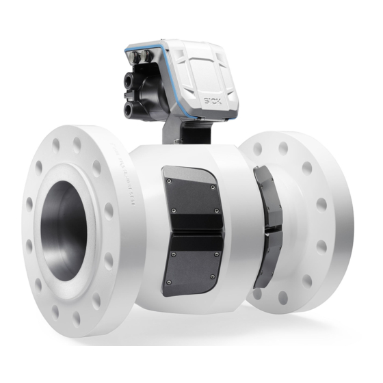
Ultrasonic gas meter
Hide thumbs
Also See for FLOWSIC600-XT:
- Operating instructions manual (154 pages) ,
- Operating instructions manual (164 pages)

Related Manuals for SICK FLOWSIC600-XT


Summary of Contents for SICK FLOWSIC600-XT
- Page 1 Title Page S E R V I C E M A N U A L FLOWSIC600-XT Ultrasonic Gas Meter Maintenance Inspection Repairs...
- Page 2 Please contact SICK Engineering GmbH or your local representa- tive in case of doubt. Legal Information Subject to change without notice. © SICK Engineering GmbH. All rights reserved. FLOWSIC600-XT · Service Manual · 8019179/V 0-2/2016-03 · © SICK Engineering GmbH...
- Page 3 Risk or hazardous situation which could result in severe personal injury or death. CAUTION Hazard or unsafe practice which could result in less severe or minor injuries. NOTICE Hazard which could result in property damage. FLOWSIC600-XT · Service Manual · 8019179/V 0-2/2016-03 · © SICK Engineering GmbH...
-
Page 4: Table Of Contents
FLOWSIC600-XT Quatro ........ - Page 5 Transducer covers ............61 FLOWSIC600-XT · Service Manual · 8019179/V 0-2/2016-03 · © SICK Engineering GmbH...
- Page 6 Component placement specification SPU (sensor cables) ..... . . 64 FLOWSIC600-XT · Service Manual · 8019179/V 0-2/2016-03 · © SICK Engineering GmbH...
-
Page 7: Important Information
Important Information FLOWSIC600-XT Important Information About this document For your safety FLOWSIC600-XT · Service Manual · 8019179/V0-2/2016-03 · © SICK Engineering GmbH... -
Page 8: About This Document
The Service Manual may therefore only be used together with the valid Operating Instruc- tions. FLOWSIC600-XT · Service Manual · 8019179/V 0-2/2016-03 · © SICK Engineering GmbH... -
Page 9: For Your Safety
1.2.1 The measuring system FLOWSIC600-XT is used for measuring the actual volumetric flow rate of gases transported in pipelines. Apart from that, the FLOWSIC600-XT can also deter- mine the actual corrected volume and the sound velocity. The measuring system shall only be used as specified by the manufacturer and as set forth below. -
Page 10: General Safety Instructions And Protective Measures
Improper use or handling can cause health or material damage. Please therefore read this Section thoroughly and observe this information during all tasks on the FLOWSIC600-XT as well as the warning and caution information in the individual Sections of this Service Man- ual. -
Page 11: Hazard Through Heavy Loads
Important Information Hazard through heavy loads 1.2.5 The FLOWSIC600-XT measuring system must be attached securely to the carrying structure when being transported and installed. ▸ Only use lifting gear and equipment (e.g. lifting straps) suitable for the weight to be lifted. - Page 12 Important Information FLOWSIC600-XT · Service Manual · 8019179/V 0-2/2016-03 · © SICK Engineering GmbH...
-
Page 13: Components
Components FLOWSIC600-XT Components Complete overview of the device family SPU (Signal Processing Unit) overview FLOWSIC600-XT · Service Manual · 8019179/V0-2/2016-03 · © SICK Engineering GmbH... -
Page 14: Complete Overview Of The Device Family
340 Sensor cover 190 Meter body type plate 400 Pressure sensor 200 SPU 410 pT sensor set 240 SPU neck assembly set 420 pT sensor cover 250 SPU neck FLOWSIC600-XT · Service Manual · 8019179/V 0-2/2016-03 · © SICK Engineering GmbH... -
Page 15: Flowsic600-Xt Forte
340 Sensor cover 190 Meter body type plate 400 Pressure sensor 200 SPU 410 pT sensor set 240 SPU neck assembly set 420 pT sensor cover 250 SPU neck FLOWSIC600-XT · Service Manual · 8019179/V0-2/2016-03 · © SICK Engineering GmbH... -
Page 16: Flowsic600-Xt 2Plex
340 Sensor cover 190 Meter body type plate 400 Pressure sensor 200 SPU 410 pT sensor set 240 SPU neck assembly set 420 pT sensor cover 250 SPU neck FLOWSIC600-XT · Service Manual · 8019179/V 0-2/2016-03 · © SICK Engineering GmbH... -
Page 17: Flowsic600-Xt Quatro
340 Sensor cover 190 Meter body type plate 400 Pressure sensor 200 SPU 410 pT sensor set 240 SPU neck assembly set 420 pT sensor cover 250 SPU neck FLOWSIC600-XT · Service Manual · 8019179/V0-2/2016-03 · © SICK Engineering GmbH... -
Page 18: Spu (Signal Processing Unit) Overview
Components SPU (Signal Processing Unit) overview 2. 2 The SPU enclosure of the FLOWSIC600-XT comprises a flameproof enclosure and an adjacent separate chamber. Ex-d enclosure version 2.2.1 Fig. 5 Exploded view Ex-d 1 Flameproof enclosure with I/O electronics 2 Ex-d terminal compartment cover... -
Page 19: Ex-De Enclosure Version
With Ex-e wiring, the Ex-d inputs and outputs run through a line duct to the Ex-e terminals in the Ex-e terminal compartment. The type of the line duct depends on the I/O configuration. FLOWSIC600-XT · Service Manual · 8019179/V0-2/2016-03 · © SICK Engineering GmbH... -
Page 20: Ex-I Enclosure Version
1 Flameproof enclosure 2 Ex-d terminal compartment cover 3 Ex-i terminal compartment 4 Ex-i terminal compartment cover 5 Ex-i transducer electronics with cover and backup battery 6 Display unit FLOWSIC600-XT · Service Manual · 8019179/V 0-2/2016-03 · © SICK Engineering GmbH... -
Page 21: Repairs
Repairs FLOWSIC600-XT Repairs General information Tools required Working on the meter body Working on the SPU FLOWSIC600-XT · Service Manual · 8019179/V0-2/2016-03 · © SICK Engineering GmbH... -
Page 22: General Information
▸ Record all work carried out in a repair protocol. ▸ Send the repair protocol to SICK to update the Data books at the factory. FLOWSIC600-XT · Service Manual · 8019179/V 0-2/2016-03 · © SICK Engineering GmbH... -
Page 23: Tools Required
● Sensor puller (Part No. 7041772) ● Coax connection tool (Part No. 4047938) ● SW 22 torque wrench, setting range up to 10 Nm) ● Adjustable wrench (8") ● Wrench, 19 mm FLOWSIC600-XT · Service Manual · 8019179/V0-2/2016-03 · © SICK Engineering GmbH... -
Page 24: Working On The Meter Body
Protect the plug against dirt as necessary, e.g. with insulating tape. Ensure the requirements for explosion protection are complied with 3 Loosen the retaining screws with a size 19 bit (ratchet or socket wrench). FLOWSIC600-XT · Service Manual · 8019179/V 0-2/2016-03 · © SICK Engineering GmbH... - Page 25 6 Turn the knurled nut until the sensor can be pulled out of the sensor sup- port. 7 Unscrew the sensor from the sensor puller FLOWSIC600-XT · Service Manual · 8019179/V0-2/2016-03 · © SICK Engineering GmbH...
-
Page 26: Fit The New Sensor
10 After sensor replacement, perform a leak tightness check. Apply leak detection spray to the sensors and slowly increase the pressure in the device. FLOWSIC600-XT · Service Manual · 8019179/V 0-2/2016-03 · © SICK Engineering GmbH... - Page 27 15 First slightly tighten the 4 screws with an SW 4 Allen key. 16 Then tighten crosswise by hand (5 Nm). FLOWSIC600-XT · Service Manual · 8019179/V0-2/2016-03 · © SICK Engineering GmbH...
-
Page 28: Replacing The Integrated P/T Sensor
4 Push the sensor cable with plug into the socket wrench 5 Position the socket wrench and turn the PT sensor out. 6 Take the PT sensor out of the meter body. FLOWSIC600-XT · Service Manual · 8019179/V 0-2/2016-03 · © SICK Engineering GmbH... -
Page 29: Fit The New P/T Sensor
6 Connect the plug connection again. 7 Fold the sensor cable as small as possible so that it is not crimped under the sensor cap. FLOWSIC600-XT · Service Manual · 8019179/V0-2/2016-03 · © SICK Engineering GmbH... - Page 30 Repairs 8 Position the sensor cover from the top downwards. 9 First slightly tighten the 4 screws. 10 Then tighten crosswise hand-tight (5 Nm). FLOWSIC600-XT · Service Manual · 8019179/V 0-2/2016-03 · © SICK Engineering GmbH...
-
Page 31: Working On The Spu
Swivel the display unit downwards 3.5.1.1 1 Open the display cover. 2 Loosen the 4 screws on the display unit with an SW 3 Allen key. 3 Carefully swivel the display unit downwards. FLOWSIC600-XT · Service Manual · 8019179/V0-2/2016-03 · © SICK Engineering GmbH... -
Page 32: Remove The Display Unit
This obviates any additional pro- tection against the unit dropping down during the work step. FLOWSIC600-XT · Service Manual · 8019179/V 0-2/2016-03 · © SICK Engineering GmbH... -
Page 33: Fit The New Display Unit
3 Position the retaining screws and small plates on the swivel joint of the electronics and screw tight. Check the small retaining plates are positioned correctly (straight side towards the hinge). FLOWSIC600-XT · Service Manual · 8019179/V0-2/2016-03 · © SICK Engineering GmbH... -
Page 34: Connect The Display Unit
Swivel the display unit upwards and screw tight 3.5.1.5 1 Swivel the display unit upwards. 2 Tighten the 4 screws on the display unit with an SW 4 Allen key (5 Nm). FLOWSIC600-XT · Service Manual · 8019179/V 0-2/2016-03 · © SICK Engineering GmbH... -
Page 35: Replacing The Display Cover
4 Position the display cover in the swivel joint. 5 Fix the new display cover with the pins. 6 Refit the display unit, → p. 33, §3.5.1.3. FLOWSIC600-XT · Service Manual · 8019179/V0-2/2016-03 · © SICK Engineering GmbH... -
Page 36: Replacing The Backup Battery
4 Insert the backup battery in the holder and connect to the “BAT2” connection. 5 Swivel the display unit back up and screw tight, → p. 34, §3.5.1.5. FLOWSIC600-XT · Service Manual · 8019179/V 0-2/2016-03 · © SICK Engineering GmbH... -
Page 37: Replacing The Rtc Battery
1 Take the RTC battery out of the holder 2 Insert the new battery. 3 Refit the battery cover. 4 Swivel the display unit back up and screw tight, → p. 34, §3.5.1.5. FLOWSIC600-XT · Service Manual · 8019179/V0-2/2016-03 · © SICK Engineering GmbH... -
Page 38: Replacing The Spu Circuit Board
– Remove the display unit, → p. 32, §3.5.1.2, step 1 and 2 Remove the electronics cover 3.5.5.1 1 Loosen the 4 screws of the electron- ics cover with a T20 Torx key. 2 Take the electronics cover off. FLOWSIC600-XT · Service Manual · 8019179/V 0-2/2016-03 · © SICK Engineering GmbH... -
Page 39: Remove The Spu Circuit Board
Replace cables when any damage can be seen. 7 Carefully remove the SPU circuit board. – Take care not to damage the con- nections on the front side of the circuit board. FLOWSIC600-XT · Service Manual · 8019179/V0-2/2016-03 · © SICK Engineering GmbH... -
Page 40: Fit The New Spu Circuit Board
5 Insert the circuit board. 6 Screw the 5 retaining screws tight (1 Nm) with T10 Torx key. FLOWSIC600-XT · Service Manual · 8019179/V 0-2/2016-03 · © SICK Engineering GmbH... -
Page 41: Fit The Electronics Cover
Make sure the cable is not crimped. 3 Tighten the 4 screws of the electron- ics cover with a T20 Torx key. 4 Connect the display unit again and close. → p. 34, §3.5.1.4. FLOWSIC600-XT · Service Manual · 8019179/V0-2/2016-03 · © SICK Engineering GmbH... -
Page 42: Replacing The Ex-D I/O Block
Remove the Ex-d I/O block 3.5.6.2 1 Disconnect terminal connections in use on the Ex-d electronics block. 2 Loosen the 3 screw fittings of the I/O block with a Phillips screwdriver. FLOWSIC600-XT · Service Manual · 8019179/V 0-2/2016-03 · © SICK Engineering GmbH... - Page 43 – Take care not to damage the cable gland in the Ex-e terminal compartment. – Carefully push the cables upwards and move the I/O block past the cables. FLOWSIC600-XT · Service Manual · 8019179/V0-2/2016-03 · © SICK Engineering GmbH...
-
Page 44: Fit The New Ex-D I/O Block
3 Insert the 3 screws and screw tight. Take care that the cutting ring washers do not drop down. 4 Connect the electrics as described in §3.4 “Electrical Installation” in the FLOWSIC600-XT Operating Instructions. FLOWSIC600-XT · Service Manual · 8019179/V 0-2/2016-03 · © SICK Engineering GmbH... -
Page 45: Close The Ex-D Terminal Compartment
2 Insert the securing screw on the Ex-d terminal compartment cover and screw tight with an SW 10 Allen key. Do not operate the device without the securing screw! FLOWSIC600-XT · Service Manual · 8019179/V0-2/2016-03 · © SICK Engineering GmbH... -
Page 46: Replacing The Ex-D I/O Block Fuse
3 Insert the new fuse. Take care not to bend the pins. 4 Make sure the fuse has a tight seat. 5 Close the Ex-d terminal compartment again → p. 45, §3.5.6.4. FLOWSIC600-XT · Service Manual · 8019179/V 0-2/2016-03 · © SICK Engineering GmbH... -
Page 47: Replacing The Ex-E Connection Block
3.5.8.1 1 Loosen the 3 screws (captive) of the Ex-e terminal compartment cover with an SW 4 Allen key. 2 Put the terminal compartment cover in the holder provided. FLOWSIC600-XT · Service Manual · 8019179/V0-2/2016-03 · © SICK Engineering GmbH... -
Page 48: Remove The Connection Blocks In The Ex-E Terminal Compartment
3 Fit the second bracket and fix with the screws (1 Nm). 4 Connect the electrics as described in §3.4 “Electrical Installation” in the FLOWSIC600-XT Operating Instructions. FLOWSIC600-XT · Service Manual · 8019179/V 0-2/2016-03 · © SICK Engineering GmbH... -
Page 49: Close The Ex-E Terminal Compartment
1 Position the cover on the Ex-e termi- nal compartment. 2 Tighten the 3 screws (captive) of the terminal compartment cover with an SW 4 Allen key (5 Nm). FLOWSIC600-XT · Service Manual · 8019179/V0-2/2016-03 · © SICK Engineering GmbH... -
Page 50: Replacing The Cable Gland Between The Ex-D And Ex-E Terminal Compartments
Hold the cable gland tight when loos- ening the snap ring so that it does not slip down. 3 Remove the cable gland downwards through the Ex-d terminal compart- ment. FLOWSIC600-XT · Service Manual · 8019179/V 0-2/2016-03 · © SICK Engineering GmbH... -
Page 51: Fit The Ex-E Cable Gland
5 Connect the electrics as described in §3.4 “Electrical Installation” in the FLOWSIC600-XT Operating Instructions. 6 Close the Ex-e terminal compartment again, → p. 49, §3.5.8.4. FLOWSIC600-XT · Service Manual · 8019179/V0-2/2016-03 · © SICK Engineering GmbH... -
Page 52: Transducer Electronics
1 Loosen the 3 long screws of the main board. 2 Loosen the snap ring of the cable gland with the snap ring pliers. 3 Remove the main board with cable gland. FLOWSIC600-XT · Service Manual · 8019179/V 0-2/2016-03 · © SICK Engineering GmbH... -
Page 53: Fit The New Cable Gland
5 Make sure the snap ring engages properly in the groove. 6 Refit the Ex-d I/O block,→ p. 44, §3.5.6.3. 7 Refit the SPU circuit board, → p. 40, §3.5.5.3. FLOWSIC600-XT · Service Manual · 8019179/V0-2/2016-03 · © SICK Engineering GmbH... -
Page 54: Parameter Input
Configure sensor settings after transducer exchange 3.6.1 In order to configure settings after exchanging a transducer pair, follow these steps: 1 Open a FLOWSIC600-XT meter using the Device Manager with user level "Service" or higher. 2 Navigate to "Service"/"Register Tree". -
Page 55: Configure Stacking
Configure Stacking 3.6.3 In order to configure Stacking of signals, please follow these steps: 1 Open a FLOWSIC600-XT meter using the device manager with user level "Service" or higher. 2 Navigate to "Diagnostics"/"Signal View". 3 Ensure, that configuration mode is set on meter. - Page 56 Repairs FLOWSIC600-XT · Service Manual · 8019179/V 0-2/2016-03 · © SICK Engineering GmbH...
-
Page 57: Accessories And Spare Parts
Accessories and Spare Parts FLOWSIC600-XT Accessories and Spare Parts SPU Parts Electronic boards Transducers Pressure/Temperature sensors O-rings for transducers Electronics accessories Transducer covers Covers p/T sensor Accessories meter body FLOWSIC600-XT · Service Manual · 8019179/V0-2/2016-03 · © SICK Engineering GmbH... -
Page 58: Spu Parts
Electronic board; 135kHz; IIC; 8path 2085297 Electronic board; 135kHz; IIA; 8path; HS 2085298 Electronic board; 80kHz; IIA; 8path 2085315 I/O unit with Ethernet 2085305 I/O unit with Ethernet 2085302 Fuse I/O unit FLOWSIC600-XT · Service Manual · 8019179/V 0-2/2016-03 · © SICK Engineering GmbH... -
Page 59: Transducers
6050602 Interface converter USB/IR 2085329 Set cable glands / blind plugs Ex-e 2085330 Backup battery unit 2085319 RTC backup battery On request Set of screws for Fl600-XT SPU housing FLOWSIC600-XT · Service Manual · 8019179/V0-2/2016-03 · © SICK Engineering GmbH... -
Page 60: Transducer Covers
Transducer cover, SS, 20"-A 2085238 Transducer cover, SS, 20"-B 2085239 Transducer cover, SS, 22"-A 2085240 Transducer cover, SS, 22"-B 2085241 Transducer cover, SS, 24"-A 2085242 Transducer cover, SS, 24"-B FLOWSIC600-XT · Service Manual · 8019179/V 0-2/2016-03 · © SICK Engineering GmbH... -
Page 61: Covers P/T Sensor
8"-16"; stainless steel Accessories meter body 4 . 9 Order number Description On request Meterbody parts for transport and storage On request Set of screws for Fl600-XT meter body FLOWSIC600-XT · Service Manual · 8019179/V0-2/2016-03 · © SICK Engineering GmbH... - Page 62 Accessories and Spare Parts FLOWSIC600-XT · Service Manual · 8019179/V 0-2/2016-03 · © SICK Engineering GmbH...
-
Page 63: Annex
Annex FLOWSIC600-XT Annex Component placement specification SPU (sensor cables) FLOWSIC600-XT · Service Manual · 8019179/V0-2/2016-03 · © SICK Engineering GmbH... -
Page 64: Component Placement Specification Spu (Sensor Cables)
Annex Component placement specification SPU (sensor cables) 5. 1 Bild 8 4-Path devices: FLOWSIC600-XT (Single), FLOWSIC600-XT 2plex and Quatro, measuring system 1 p&T FLOWSIC600-XT · Service Manual · 8019179/V 0-2/2016-03 · © SICK Engineering GmbH... - Page 65 Annex Bild 9 FLOWSIC600-XT 2plex, measuring system 2 (1-Path) p&T FLOWSIC600-XT · Service Manual · 8019179/V0-2/2016-03 · © SICK Engineering GmbH...
- Page 66 Annex Bild 10 FLOWSIC600-XT Quatro, measuring system 2 p&T FLOWSIC600-XT · Service Manual · 8019179/V 0-2/2016-03 · © SICK Engineering GmbH...
- Page 67 Annex Bild 11 FLOWSIC600-XT Forte, measuring system 1 and 2 FLOWSIC600-XT · Service Manual · 8019179/V0-2/2016-03 · © SICK Engineering GmbH...
- Page 68 E-Mail sales@sick.co.nz United Arab Emirates China Norway E-Mail sick@sick.no USA/Mexico Denmark Poland E-Mail sick@sick.dk Finland Romania Vietnam France Russia Gemany Singapore Great Britain Slovakia E-Mail mail@sick-sk.sk Hong Kong Slovenia Hungary South Africa www.sick.com SICK AG | Waldkirch | Germany | www.sick.com...
Need help?
Do you have a question about the FLOWSIC600-XT and is the answer not in the manual?
Questions and answers