
Related Manuals for SICK FLOWSIC100 Flare-XT


Summary of Contents for SICK FLOWSIC100 Flare-XT
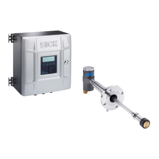
- Page 1 Main O P E R A T I N G I N S T R U C T I O N S FLOWSIC100 Flare-XT Ultrasonic Mass Flow Measuring Device Installation Operation Maintenance...
- Page 2 NOTICE Hazard which could result in property damage. Information symbols Important technical information for this product Supplementary information Link referring to information at another place FLOWSIC100 Flare-XT · Operating Instructions · 8023761/V 1-0/2020-10 · © SICK Engineering GmbH...
-
Page 3: Table Of Contents
Restrictions on use............35 FLOWSIC100 Flare-XT · Operating Instructions · 8023761/V 1-0/2020-10 · © SICK Engineering GmbH... - Page 4 Restrictions on use ............89 FLOWSIC100 Flare-XT · Operating Instructions · 8023761/V 1-0/2020-10 · © SICK Engineering GmbH...
- Page 5 Connect to the device ........... . 123 FLOWSIC100 Flare-XT · Operating Instructions · 8023761/V 1-0/2020-10 · © SICK Engineering GmbH...
- Page 6 Starting a diagnostic session ..........148 10.4 FLOWSIC100 Flare-XT · Operating Instructions · 8023761/V 1-0/2020-10 · © SICK Engineering GmbH...
- Page 7 System FLOWSIC100 Flare-XT ........
- Page 8 Cont ents FLOWSIC100 Flare-XT · Operating Instructions · 8023761/V 1-0/2020-10 · © SICK Engineering GmbH...
-
Page 9: About This Document
About this document FLOWSIC100 Flare-XT About this document Function of this document Scope of application Target groups Data integrity Further information FLOWSIC100 Flare-XT · Operating Instructions · 8023761/V 1-0/2020-10 · © SICK Engineering GmbH... -
Page 10: Function Of This Document
In all cases, the customer is responsible for the implementation of safety measures suit- able for the respective situation, e.g., network separation, firewalls, virus protection and patch management. FLOWSIC100 Flare-XT · Operating Instructions · 8023761/V 1-0/2020-10 · © SICK Engineering GmbH... -
Page 11: Further Information
About this document Further information 1 .5 NOTICE: Observe all supplied documents. FLOWSIC100 Flare-XT · Operating Instructions · 8023761/V 1-0/2020-10 · © SICK Engineering GmbH... - Page 12 About this document FLOWSIC100 Flare-XT · Operating Instructions · 8023761/V 1-0/2020-10 · © SICK Engineering GmbH...
-
Page 13: For Your Safety
For your safety FLOWSIC100 Flare-XT For your safety Basic safety information Intended use FLOWSIC100 Flare-XT · Operating Instructions · 8023761/V 1-0/2020-10 · © SICK Engineering GmbH... -
Page 14: Basic Safety Information
Only use the FLOWSIC100 Flare-XT measuring system as described in these Operating Instructions. The manufacturer bears no responsibility for any other use. ▸ Do not attempt any work on or repairs to the FLOWSIC100 Flare-XT unless described in this Manual. ▸... -
Page 15: System Description
System description FLOWSIC100 Flare-XT System description System components Functional principle System configuration FLOWSIC100 Flare-XT · Operating Instructions · 8023761/V 1-0/2020-10 · © SICK Engineering GmbH... -
Page 16: System Components
● Flow calibrated (the complete measuring system has been calibrated on a flow test bench.) Both variants reduce measurement uncertainty. ● External temperature and pressure transmitters available on request FLOWSIC100 Flare-XT · Operating Instructions · 8023761/V 1-0/2020-10 · © SICK Engineering GmbH... -
Page 17: Functional Principle
The correct evaluation of the Reynolds number is decisive for the determination of the correct calibration function. The Reynolds number must be determined with an accuracy of 20% in order to achieve the device accuracy offered by SICK. FLOWSIC100 Flare-XT · Operating Instructions · 8023761/V 1-0/2020-10 · © SICK Engineering GmbH... -
Page 18: System Overview
1 Sender/receiver unit FLSE-XT Master Temperature sensor 2 Connection cable Pressure sensor 3 Weatherproof cover for Interface Unit Sender/receiver unit FLSE-XT Slave 4 Interface Unit Optional spool piece FLOWSIC100 Flare-XT · Operating Instructions · 8023761/V 1-0/2020-10 · © SICK Engineering GmbH... -
Page 19: System Configuration
System description System configuration 3 .4 FLOWSIC100 Flare-XT is available as 1- or 2-path measuring system. The following Figures show cross-duct installations (F1F-S, F1F-M, F1F-H). In principle, the configuration also applies to one-sided installation (F1F-P). Configuration Description Two sender/receiver units are mounted on the pipeline. -
Page 20: Asc Technology (Patented) - Active Sound Correlation Technology
“Extended VOG Range” is signalled in the path status of FLOWgate when the ASC technology is active. Fig. 4 Signaling “Extended VOG Range” in the path status FLOWSIC100 Flare-XT · Operating Instructions · 8023761/V 1-0/2020-10 · © SICK Engineering GmbH... -
Page 21: Project Planning
Project planning FLOWSIC100 Flare-XT Project planning Overview Determining the measuring and installation location for FLSE100-XT Determining the installation location of the Interface Unit FLOWSIC100 Flare-XT · Operating Instructions · 8023761/V 1-0/2020-10 · © SICK Engineering GmbH... -
Page 22: Overview
Material of duct probe and transducer Evaluation Sheet Fitting locations Cable lengths Plan power Operating voltage, Plan adequate cable cross-sections and supply power requirements According to Technical Data fuses FLOWSIC100 Flare-XT · Operating Instructions · 8023761/V 1-0/2020-10 · © SICK Engineering GmbH... -
Page 23: Determining The Measuring And Installation Location For Flse100-Xt
Inlet and reduced compared to 1-path measurement with the same measurement uncertainty. Measuring outlet piping ● SICK offers expertise support for optimal adjustment of the meter for the given inlet and outlet location lengths piping conditions. Pipelines with vertical, horizontal or inclined direction Pipelines with horizontal or vertical direction ●... -
Page 24: Additional Requirements For Optional Spool Piece
Fig. 5 Installation location Top view 1 Sender/receiver unit FLSE-XT Master 2 Pressure sensor 3 Temperature sensor 4 Sender/receiver unit FLSE-XT Slave =Diameter of thermowell FLOWSIC100 Flare-XT · Operating Instructions · 8023761/V 1-0/2020-10 · © SICK Engineering GmbH... -
Page 25: Applications With Wet Gas
● Isolate the nozzle pipe to reduce dew point underruns (only for low gas temperatures < 100 °C). Clearance for fitting and removing the sender/receiver units 4.2.5 NOTICE: Observe the dimension drawings in p. 167, §12.8.1. FLOWSIC100 Flare-XT · Operating Instructions · 8023761/V 1-0/2020-10 · © SICK Engineering GmbH... -
Page 26: Determining The Installation Location Of The Interface Unit
NOTICE: The Interface Unit is only suitable for vertical installation. Clearance for fitting the Interface Unit 4.3.2 NOTICE: Observe the dimension drawings in p. 169, §12.8.2. FLOWSIC100 Flare-XT · Operating Instructions · 8023761/V 1-0/2020-10 · © SICK Engineering GmbH... -
Page 27: Installation Flse100-Xt
Installation FLSE100-XT FLOWSIC100 Flare-XT Installation FLSE100-XT Intended use Product description Installation Electrical installation FLOWSIC100 Flare-XT · Operating Instructions · 8023761/V 1-0/2020-10 · © SICK Engineering GmbH... -
Page 28: Intended Use
All regulations/special regulations that can be applicable for the plant must be observed. FLOWSIC100 Flare-XT · Operating Instructions · 8023761/V 1-0/2020-10 · © SICK Engineering GmbH... -
Page 29: Hazard Through Electrical Equipment
Use appropriate caution when performing maintenance and cleaning work. For example, the surfaces should only be cleaned with a damp cloth. The respective devices will be identified by the manufacturer with a warning sign. FLOWSIC100 Flare-XT · Operating Instructions · 8023761/V 1-0/2020-10 · © SICK Engineering GmbH... -
Page 30: Retraction Mechanism Of The Sender/Receiver Units
This connection is closed with a blind plug at the factory. ▸ The blind plug may only be removed when a venting valve is installed, p. 76, §5.6.10. FLOWSIC100 Flare-XT · Operating Instructions · 8023761/V 1-0/2020-10 · © SICK Engineering GmbH... -
Page 31: Operation In Potentially Explosive Atmospheres
Class I, Zone 1, Ex/AEx d[ia] IIB + H2, T4; Class I, Division 2, Groups A, B, C and D, T4; Class I, Zone 2, Ex/AEx nA[ia] IIC, T4 FLOWSIC100 Flare-XT · Operating Instructions · 8023761/V 1-0/2020-10 · © SICK Engineering GmbH... -
Page 32: Specific Conditions
Optionally minimum ambient temperature -50 °C – Ambient pressure 80 kPa (0.8 bar) to 110 kPa (1.1 bar) – Air with normal oxygen content, typically 21 percent by volume. FLOWSIC100 Flare-XT · Operating Instructions · 8023761/V 1-0/2020-10 · © SICK Engineering GmbH... -
Page 33: Temperature
… +195 °C -196 … +70 °C -50 … +70 °C -196 … +280 °C -196 … +70 °C -50 … +70 °C For F1F-H: -70 °C FLOWSIC100 Flare-XT · Operating Instructions · 8023761/V 1-0/2020-10 · © SICK Engineering GmbH... -
Page 34: Warning Information On Device
– Degree of protection – Fitting instructions – Area definition ▸ Regulations to be applied: – IEC 60079-14 – IEC 60079-17 or comparable national regulations. FLOWSIC100 Flare-XT · Operating Instructions · 8023761/V 1-0/2020-10 · © SICK Engineering GmbH... -
Page 35: Restrictions On Use
Leak tightness is to be checked regularly during operation and the seal replaced, as required. ● Before every re-installation new seals have to be used in the required design. FLOWSIC100 Flare-XT · Operating Instructions · 8023761/V 1-0/2020-10 · © SICK Engineering GmbH... - Page 36 Zone 0. The wall must be thicker than 3 mm. The requirements in EN 60079-26 Section 4.6 must be adhered to. FLOWSIC100 Flare-XT · Operating Instructions · 8023761/V 1-0/2020-10 · © SICK Engineering GmbH...
-
Page 37: Product Description
Example of marking plate passive (SLAVE) FLSE100-XT-S (ATEX/IECEx) Fig. 7 Type plate example FLSE100-XT-M Example of marking plate FLSE100-XT-M (ATEX/IECEx) Example of marking plate passive (SLAVE) FLSE100-XT-M (ATEX/IECEx) FLOWSIC100 Flare-XT · Operating Instructions · 8023761/V 1-0/2020-10 · © SICK Engineering GmbH... - Page 38 Type plate example FLSE100-XT-H Example of marking plate FLSE100-XT-H (ATEX/IECEx) Example of marking plate passive (SLAVE) FLSE100-XT-H (ATEX/IECEx) Type plate example FLSE100-XT-P Fig. 9 Example of marking plate FLSE100-XT- (ATEX/IECEx) FLOWSIC100 Flare-XT · Operating Instructions · 8023761/V 1-0/2020-10 · © SICK Engineering GmbH...
-
Page 39: Sender/Receiver Units
Retraction nozzle 2 Electronics unit Duct probe 3 T-connector Sensor contour 4 TNC connector (connection for Slave) Transducer 5 Self-cutting ring 10 TNC connector (connection for Master) FLOWSIC100 Flare-XT · Operating Instructions · 8023761/V 1-0/2020-10 · © SICK Engineering GmbH... - Page 40 1 Pressure compensation element 5 Retraction nozzle 2 Electronics unit 6 Duct probe 3 Cable gland (connection for Slave) 7 Sensor contour 4 Self-cutting ring 8 Transducer FLOWSIC100 Flare-XT · Operating Instructions · 8023761/V 1-0/2020-10 · © SICK Engineering GmbH...
- Page 41 1 Pressure compensation element 6 Retraction nozzle 2 Electronics unit 7 Duct probe 3 T-connector 8 Transducer 4 Pressure compensation element 9 Sensor contour 5 Self-cutting ring FLOWSIC100 Flare-XT · Operating Instructions · 8023761/V 1-0/2020-10 · © SICK Engineering GmbH...
-
Page 42: Material For Parts With Process Gas Contact
6 Retraction nozzle 15 Thrust ring 7 Retraction flange 16 Probe tube 8 Transducer 17 Transducer pipe screw fitting 9 Sensor contour 18 Transducer and contour holder FLOWSIC100 Flare-XT · Operating Instructions · 8023761/V 1-0/2020-10 · © SICK Engineering GmbH... -
Page 43: Spool Piece Option
Spool piece option 5 .4 The FLOWSIC100 Flare-XT can also be fitted with an optional spool piece to reduce geometric uncertainty of device installation and to simplify assembly. The exact design (nominal diameter, connection, material) always depends on the customer specifications. -
Page 44: Transport And Storage
Anticorit spray (not required for spool pieces made of stainless steel). Do the same if the meter must be stored in dry conditions, but for more than a week. FLOWSIC100 Flare-XT · Operating Instructions · 8023761/V 1-0/2020-10 · © SICK Engineering GmbH... - Page 45 During transport, the spool piece must not be turned over or start to swing. Fig. 17 Lifting requirements (installed sender/receiver units are not shown) Max. 60 ° FLOWSIC100 Flare-XT · Operating Instructions · 8023761/V 1-0/2020-10 · © SICK Engineering GmbH...
-
Page 46: Installation
To ensure safe and reliable operation of the measuring devices, ensure that the current operating conditions on the system correspond to the specifications on the type plates of the sender/receiver units. FLOWSIC100 Flare-XT · Operating Instructions · 8023761/V 1-0/2020-10 · © SICK Engineering GmbH... -
Page 47: Fitting The Spool Piece (Option)
Install the pressure measurement line between the pressure tapping point (option) and the pressure sensor (option). Perform a leak tightness check with suitable means after completion of the installation work, p. 74, §5.6.8.4. FLOWSIC100 Flare-XT · Operating Instructions · 8023761/V 1-0/2020-10 · © SICK Engineering GmbH... -
Page 48: Installation Sequence
– For retractable installation: Ball valve length – Nozzle angle – Additionally for cross-duct versions: Probe offset a ● Gemometric installation parameters for commissioning the measuring system, p. 65, §5.6.8.1. FLOWSIC100 Flare-XT · Operating Instructions · 8023761/V 1-0/2020-10 · © SICK Engineering GmbH... -
Page 49: Installation Accessories
It must be ensured that the temperature of the nozzle and ball valve is not so high that the material strength can no longer be guaranteed when derating the pressure over the temperature, p. 165, §12.7. FLOWSIC100 Flare-XT · Operating Instructions · 8023761/V 1-0/2020-10 · © SICK Engineering GmbH... -
Page 50: Nozzles, Blind Flanges And Seals
These seals are included in the standard scope of delivery of the ball valve and/or sender/receiver unit. Table 5 Available seals Material Temperature range Serrated gasket B9A 1.4571 -196 … +280°C FLOWSIC100 Flare-XT · Operating Instructions · 8023761/V 1-0/2020-10 · © SICK Engineering GmbH... -
Page 51: Ball Valve
5.6.6.2 The ball valve serves for safe separation of the sender/receiver units from the process and is required when the sender/receiver units are to be dismounted during the process. SICK recommends using a ball valve. Ball valves for various flange connections (Cl150, CL300, PN25 DN50) and temperature ranges) are available. -
Page 52: Nozzle Installation Tool
Installation FLSE100-XT Nozzle installation tool 5.6.6.3 The installation tool serves to align and weld the nozzle on the pipeline. SICK offers various nozzle installation tools depending on the nominal pipe diameter and path configuration. The nozzle installation tool contains, per nozzle ●... -
Page 53: Fitting The Nozzles On The Pipeline (Measuring System Without Spool Piece Option)
3) Loosen the fastening, take the strip off and lay it out on a level surface. For 1-path measurements, fold the strip to the overlap line so that the part matching pipe circumference (U) is halved. Overlap line FLOWSIC100 Flare-XT · Operating Instructions · 8023761/V 1-0/2020-10 · © SICK Engineering GmbH... -
Page 54: Determining The Nozzle Position For Cross-Duct Versions
5) Draw guide lines (1) for the nozzle positions with the previously calculated nozzle offset a, mark crossing points (2) and draw marking points (3) in distance 60 mm (x) from the crossing points. U / 2 Path 1 Path 2 FLOWSIC100 Flare-XT · Operating Instructions · 8023761/V 1-0/2020-10 · © SICK Engineering GmbH... - Page 55 Path 1 Path 2 7) Take the strip off again and join the additional markings with a line. Marking lines Marking lines FLOWSIC100 Flare-XT · Operating Instructions · 8023761/V 1-0/2020-10 · © SICK Engineering GmbH...
-
Page 56: Determining The Nozzle Position For The Probe Version
5) Draw a guide line (1) for the nozzle position(s), mark crossing points (2) and draw marking points (3) in distance 80 mm (x) from the crossing points. Path 1 Path 2 FLOWSIC100 Flare-XT · Operating Instructions · 8023761/V 1-0/2020-10 · © SICK Engineering GmbH... -
Page 57: Welding The Nozzle On
A faulty welding seam can allow gas to escape from the pipeline. This can immediately lead to a dangerous situation. ▸ Ensure welding seams are gas-tight. ▸ Check strength and durable tightness of the welding seams. FLOWSIC100 Flare-XT · Operating Instructions · 8023761/V 1-0/2020-10 · © SICK Engineering GmbH... - Page 58 Slide centering plate (4) on the cone of the welding aid (1) and fasten with the nut (5). ▸ Slide nozzle (6) over threaded rod and centering plate. FLOWSIC100 Flare-XT · Operating Instructions · 8023761/V 1-0/2020-10 · © SICK Engineering GmbH...
- Page 59 – On cross-duct versions, weld the nozzle on the opposite pipeline side in the same manner and then determine distance D2. – Note measures D1 and D2; these measures are required for the geometric calculation during commissioning . FLOWSIC100 Flare-XT · Operating Instructions · 8023761/V 1-0/2020-10 · © SICK Engineering GmbH...
- Page 60 ( p. 53, §5.6.7). ▸ Only once on each nozzle. ▸ Have this work done by skilled persons specially qualified for this work. FLOWSIC100 Flare-XT · Operating Instructions · 8023761/V 1-0/2020-10 · © SICK Engineering GmbH...
- Page 61 Keep the ball valve closed and fitted until a sender/receiver unit has been fitted. ▸ Secure the ball valve against unintentional activation. ▸ Instruct other persons accordingly. FLOWSIC100 Flare-XT · Operating Instructions · 8023761/V 1-0/2020-10 · © SICK Engineering GmbH...
-
Page 62: Fitting The Sender/Receiver Units
5 Mounting kit (gasket, fastening screws, nuts, washers, centering sleeves) 2 Duct probe 6 Ball valve 3 Cutting ring screw connection 7 Nozzle 4 Retraction nozzle 8 Pipeline FLOWSIC100 Flare-XT · Operating Instructions · 8023761/V 1-0/2020-10 · © SICK Engineering GmbH... - Page 63 Fig. 32 Using the nozzle insulation set 1 Insulation sleeve 5 Flange 2 Washer 6 Fastening screw 3 Insulating disc 7 Gasket 4 Nut FLOWSIC100 Flare-XT · Operating Instructions · 8023761/V 1-0/2020-10 · © SICK Engineering GmbH...
- Page 64 SICK recommends: ● Only use the same gasket type as the original delivery. ● Apply a tightening torque according to the installed gasket, p. 185, §15.4. FLOWSIC100 Flare-XT · Operating Instructions · 8023761/V 1-0/2020-10 · © SICK Engineering GmbH...
-
Page 65: Calculating The Wetted Part Length Wl And Geometric Installation Parameters
The wL (“wetted part length”) and geometric installation parameters are calculated. NOTICE: The geometric installation parameters in the “Result: Parameters for configu- ration” area and the wall thickness are required for configuring the measuring system during commissioning. FLOWSIC100 Flare-XT · Operating Instructions · 8023761/V 1-0/2020-10 · © SICK Engineering GmbH... - Page 66 Installation FLSE100-XT Fig. 33 Installation of F1F-S, F1F-M, F1F-H (cross-duct versions) FLOWSIC100 Flare-XT · Operating Instructions · 8023761/V 1-0/2020-10 · © SICK Engineering GmbH...
- Page 67 Installation FLSE100-XT Fig. 34 Installation of F1F-P (probe version) FLOWSIC100 Flare-XT · Operating Instructions · 8023761/V 1-0/2020-10 · © SICK Engineering GmbH...
-
Page 68: Tightening The Self-Cutting Ring
Tightening the self-cutting ring 5.6.8.2 SICK recommends that the correct setting of the wetted part length and tightening the cutting ring be carried out in a workshop before installation in the pipeline. Tightening the self-cutting ring in the correct position ensures the correct wetted part length for installation in the pipeline. - Page 69 7 Completely loosen the pipe screw fitting again. 8 Loosen the cap nut again and fully retract the sender/receiver unit for transport and installation in the pipeline. FLOWSIC100 Flare-XT · Operating Instructions · 8023761/V 1-0/2020-10 · © SICK Engineering GmbH...
- Page 70 ▸ Replace the gasket if it has visible deformations, indentations or damage. In this case contact SICK Service. Otherwise there is a risk of leakage. FLOWSIC100 Flare-XT · Operating Instructions · 8023761/V 1-0/2020-10 · © SICK Engineering GmbH...
-
Page 71: Installing The Sender/Receiver Units
Before securing the self-cutting ring fitting again, align probe version F1F-P correctly: The measuring path must be aligned in flow direction, i.e. the arrow shown must point in flow direction. FLOWSIC100 Flare-XT · Operating Instructions · 8023761/V 1-0/2020-10 · © SICK Engineering GmbH... - Page 72 ±3°. To ensure this, use a laser to align probe version F1F-P: FLOWSIC100 Flare-XT · Operating Instructions · 8023761/V 1-0/2020-10 · © SICK Engineering GmbH...
- Page 73 Make sure the markings for the self-cutting ring fitting are next to each other again, → Fig. 35. Fig. 38 Alignment of probe version F1F-P Marking: 1 m Marking: 1 m 1 Laser 2 Laser beam FLOWSIC100 Flare-XT · Operating Instructions · 8023761/V 1-0/2020-10 · © SICK Engineering GmbH...
-
Page 74: Leak Tightness Check
Proceed as follows when leak tightness is not established: Pull the sender/receiver units back and disconnect them from the process by closing the ball valve, p. 75, §5.6.9. Contact SICK Service. FLOWSIC100 Flare-XT · Operating Instructions · 8023761/V 1-0/2020-10 · © SICK Engineering GmbH... -
Page 75: Pulling The Sender/Receiver Units Back
1 Cap nut (self-cutting ring fitting) 2 Pipe screw fitting WARNING: Hazardous gas (possibly explosive or toxic) Consider the gas trapped in the retraction nozzle, p. 30, §5.2.5. FLOWSIC100 Flare-XT · Operating Instructions · 8023761/V 1-0/2020-10 · © SICK Engineering GmbH... -
Page 76: Fitting The Venting Valve
Fitting the venting valve 5.6.10 A venting valve is available as an option from SICK (Order No. 2108210). Use a suitable valve with 1/8" NPT thread when the valve available from SICK is not used. WARNING: Hazard through gas in the pipeline ▸... -
Page 77: Fitting The Weatherproof Cover For The Sender/Receiver Unit
Overview 5.6.11.1 Fig. 41 Weatherproof cover overview 1 Holder 2 Safety splints 3 Weatherproof cover 4 Washers 5 Hexagon nuts 6 Round steel bow FLOWSIC100 Flare-XT · Operating Instructions · 8023761/V 1-0/2020-10 · © SICK Engineering GmbH... -
Page 78: Fitting The Weatherproof Cover
Make sure the holder is correctly aligned and the probe is not damaged. See the adjacent Figure. FLOWSIC100 Flare-XT · Operating Instructions · 8023761/V 1-0/2020-10 · © SICK Engineering GmbH... - Page 79 Installation FLSE100-XT 2 Push the weatherproof cover into the holder. 3 Fix the weatherproof cover with the four safety splints. FLOWSIC100 Flare-XT · Operating Instructions · 8023761/V 1-0/2020-10 · © SICK Engineering GmbH...
-
Page 80: Electrical Installation
F1F-H. Only use installation material approved for the applied hazard zone. The user is responsible for correct selection. FLOWSIC100 Flare-XT · Operating Instructions · 8023761/V 1-0/2020-10 · © SICK Engineering GmbH... -
Page 81: Requirements For Installation In The Ex Zone
If the transducer circuits are disconnected while energizing, it still must be observed that the safe separation from other intrinsically safe and non-intrinsically safe circuits is not overridden and thus intrinsic safety endangered. For this reason, the associated connection FLOWSIC100 Flare-XT · Operating Instructions · 8023761/V 1-0/2020-10 · © SICK Engineering GmbH... - Page 82 The cables for the intrinsically safe components are marked either with “Exi” or a blue cable covering or with blue shrink sleeves on the cable ends or with the SICK item number, at least on the associated packaging. The technical safety data are shown in the Type Examination Certificate.
-
Page 83: Connection Overview
Communication between FLSE Master and a higher level control system (Interface 1) MCX: Signal for FLSE Slave NOTICE: Self-locking terminals for wire sizes 0.5 .. 1.5 mm² (AWG20 ... AWG16). FLOWSIC100 Flare-XT · Operating Instructions · 8023761/V 1-0/2020-10 · © SICK Engineering GmbH... -
Page 84: Connection Diagrams
+24 V DC green RS485a +24 V DC yellow RS485b Terminals Connection cable FLSE100 Slave +24 V DC FLSE100-XT (passive RS485a ultrasonic transducer * RS485b *: Not for FLSE100-XT-P FLOWSIC100 Flare-XT · Operating Instructions · 8023761/V 1-0/2020-10 · © SICK Engineering GmbH... -
Page 85: Installation Interface Unit
Installation Interface Unit FLOWSIC100 Flare-XT Installation Interface Unit Intended use Safety information Product description Installation Electrical installation FLOWSIC100 Flare-XT · Operating Instructions · 8023761/V 1-0/2020-10 · © SICK Engineering GmbH... -
Page 86: Intended Use
WARNING: Hazards through explosive or ignitable gases ▸ In potentially explosive atmospheres, only use the version of the Interface Unit specified for such use ( p. 87, §6.2.5). FLOWSIC100 Flare-XT · Operating Instructions · 8023761/V 1-0/2020-10 · © SICK Engineering GmbH... -
Page 87: Hazards Through Electrostatic Discharges
Requirements on the personnel's qualification 6.2.7 ▸ Read the Operating Instructions before putting the Interface Unit into operation. FLOWSIC100 Flare-XT · Operating Instructions · 8023761/V 1-0/2020-10 · © SICK Engineering GmbH... - Page 88 – Degree of protection – Fitting instructions – Area definition ▸ Regulations to be applied: – IEC 60079-14 – IEC 60079-17 or comparable national regulations. FLOWSIC100 Flare-XT · Operating Instructions · 8023761/V 1-0/2020-10 · © SICK Engineering GmbH...
-
Page 89: Restrictions On Use
FLOWSIC100 Flare-XT · Operating Instructions · 8023761/V 1-0/2020-10 · © SICK Engineering GmbH... -
Page 90: Product Description
The type plate is located on the right side of the device. Fig. 45 Type plate ATEX (example) DC version AC version Type plate CSA (example) Fig. 46 FLOWSIC100 Flare-XT · Operating Instructions · 8023761/V 1-0/2020-10 · © SICK Engineering GmbH... -
Page 91: Type Code
Type code 6.3.2 Fig. 47 Interface Unit type code (example) - AEC A1A1S TS 1S111F N Product name Application Ex classification Mechanical properties Ambient conditions Electroncis Customized FLOWSIC100 Flare-XT · Operating Instructions · 8023761/V 1-0/2020-10 · © SICK Engineering GmbH... -
Page 92: Device Components
Enclosure base 2 Display Pressure compensation element 3 Infrared interface Exterior ground terminal 4 Display cover 10 Cable inlets 5 Screw-on tabs 11 Enclosure door 6 Electronics cover FLOWSIC100 Flare-XT · Operating Instructions · 8023761/V 1-0/2020-10 · © SICK Engineering GmbH... - Page 93 Sealing plugs NPT (optionally available with 9 cable entries) 1 Sealing plugs NPT 1/2" 2 Sealing plugs NPT 3/4" 3 Exterior ground terminal 4 Flange plate 5 Identification plates for thread size FLOWSIC100 Flare-XT · Operating Instructions · 8023761/V 1-0/2020-10 · © SICK Engineering GmbH...
-
Page 94: Device Description
Optional AC/DC Converter Uout = 24 V DC Interface Power IN 12 ... 24 V DC optional 115 .. 230 V AC IN 24 V DC Out FLOWSIC100 Flare-XT · Operating Instructions · 8023761/V 1-0/2020-10 · © SICK Engineering GmbH... -
Page 95: Interfaces
● One serial FOUNDATION Fieldbus Slave interface Detailed descriptions of the MODBUS, HART and FOUNDATION Fieldbus protocols are available as separate documents on the product CD, at www.sick.de or from SICK Service. FLOWSIC100 Flare-XT · Operating Instructions · 8023761/V 1-0/2020-10 · © SICK Engineering GmbH... -
Page 96: Installation
Do not put the interface Unit into operation if you notice any damage! Tools required 6.4.3 ● Allen keys SW 6 and 8 ● Jaw wrenches size 13, 17 and 19 ● Drill and tools for wall fitting FLOWSIC100 Flare-XT · Operating Instructions · 8023761/V 1-0/2020-10 · © SICK Engineering GmbH... -
Page 97: Fitting The Interface Unit
The distance between enclosure base and wall must be 10 mm; the wall must be flat. The air circulation behind the Interface Unit must not be obstructed. Fig. 52 General clearance to Interface Unit 15 cm FLOWSIC100 Flare-XT · Operating Instructions · 8023761/V 1-0/2020-10 · © SICK Engineering GmbH... -
Page 98: Option "Mounting Kit 2-Inch Pipe Mounting
Fitting the installation plate on the 2-inch pipe (dimensions in mm) Detail 1 Detail 1 Ø 60.3 Round steel bow DIN3570 Washer A13 -A4 Nut M12 -A4 Installation plate FLOWSIC100 Flare-XT · Operating Instructions · 8023761/V 1-0/2020-10 · © SICK Engineering GmbH... - Page 99 Fitting the Interface Unit on the installation plate Detail 2 Detail 2 Nut M10 DIN934 Washer B10.5 DIN125 Screw M10 DIN912 Holes for fitting the Interface Unit Zone 2 FLOWSIC100 Flare-XT · Operating Instructions · 8023761/V 1-0/2020-10 · © SICK Engineering GmbH...
-
Page 100: Fitting The Weatherproof Cover
Fitting the weatherproof cover on the wall Fig. 56 2 Then screw the Interface Unit also to the wall through the four holes in the weatherproof cover as marked in → Fig. 57. FLOWSIC100 Flare-XT · Operating Instructions · 8023761/V 1-0/2020-10 · © SICK Engineering GmbH... -
Page 101: Weatherproof Cover For Interface Unit For Fitting On A 2-Inch Pipe
2 Fasten the installation plate to the 2-inch pipe according to p. 98, §6.4.4.2 and → Fig. 53. 3 Screw the weatherproof cover with the supplied fastening material through the four holes marked on the mounting plate, → Fig. 58. FLOWSIC100 Flare-XT · Operating Instructions · 8023761/V 1-0/2020-10 · © SICK Engineering GmbH... - Page 102 Nut M8 DIN934 4 Also screw the Interface Unit to the installation plate through the four holes of the weatherproof cover using the supplied assembly material, → Fig. 59. FLOWSIC100 Flare-XT · Operating Instructions · 8023761/V 1-0/2020-10 · © SICK Engineering GmbH...
- Page 103 Fitting the Interface Unit on the weatherproof cover Holes for fitting the Interface Unit Zone 2 Fig. 60 Interface Unit with fitted weatherproof cover Detail Screw M10 DIN912 Washer B10.5 DIN125 Nut M10 DIN934 FLOWSIC100 Flare-XT · Operating Instructions · 8023761/V 1-0/2020-10 · © SICK Engineering GmbH...
-
Page 104: Fitting The Tag Plate (Available As Option)
– Use both shorter screws for the Interface Unit with metric cable entries (without flange plate): Fit the contact disc with one of the two screws between the screw head and tag plate. FLOWSIC100 Flare-XT · Operating Instructions · 8023761/V 1-0/2020-10 · © SICK Engineering GmbH... - Page 105 Installation Interface Unit Fig. 62 Tag plate fitted Interface Unit with metric thread Interface Unit with NPT thread FLOWSIC100 Flare-XT · Operating Instructions · 8023761/V 1-0/2020-10 · © SICK Engineering GmbH...
-
Page 106: Electrical Installation
All cable inlets or cable sealing plugs must be approved for a temperature range of -40°C ... + 60°C or -40°C ... +65°C, depending on the version. ▸ Only copper wires may be used. FLOWSIC100 Flare-XT · Operating Instructions · 8023761/V 1-0/2020-10 · © SICK Engineering GmbH... -
Page 107: Cable Glands
Depending on the variant, the inputs of the device are installed with certified cable glands or with certified sealing plugs. Use only installation material approved for the hazard zone involved. The user is responsible for correct selection. FLOWSIC100 Flare-XT · Operating Instructions · 8023761/V 1-0/2020-10 · © SICK Engineering GmbH... -
Page 108: Requirements For Installation In The Ex Zone
● The devices to be used must be checked for suitability for the application area. ● After installation, an initial test of the device and the plant according to EN/ IEC 60079-17 must be performed. FLOWSIC100 Flare-XT · Operating Instructions · 8023761/V 1-0/2020-10 · © SICK Engineering GmbH... - Page 109 Specific requirements for installation in the USA and Canada ● Installations in USA must be carried out according to NEC (ANSI/NFPA70). ● Installations in Canada must be carried out according to CEC part 1. FLOWSIC100 Flare-XT · Operating Instructions · 8023761/V 1-0/2020-10 · © SICK Engineering GmbH...
-
Page 110: Electrical Connections Of The Interface Unit
8 Field connections for I/O modules P4 - P9 – direct 17 Backup battery for real-time clock (RTC) connection to module slots 1-6 9 Field connection for ultrasonic sensors P3 – external serial 18 Terminal block grounding FLOWSIC100 Flare-XT · Operating Instructions · 8023761/V 1-0/2020-10 · © SICK Engineering GmbH... -
Page 111: Device Module Configuration
The module configuration of the respective device is marked on the sticker on the inside of the enclosure door: Fig. 65 Module configuration (example; the first line designates module slots 1-6) FLOWSIC100 Flare-XT · Operating Instructions · 8023761/V 1-0/2020-10 · © SICK Engineering GmbH... -
Page 112: Connection Area For Field-Side Wiring
GND is connected electrically with the exterior ground terminal RS485-A1 Serial interface Installation option for connection of two FLSE100-XT sender/receiver units, connection from P3 to the terminal blocks RS485-B1 must be made on-site FLOWSIC100 Flare-XT · Operating Instructions · 8023761/V 1-0/2020-10 · © SICK Engineering GmbH... - Page 113 Transmit data Serial RS232 Internal COM1, Request to send Connection Scada, Service PC Receive data or Gas chromatograph Clear to send Common Ground – connected electrically with GND FLOWSIC100 Flare-XT · Operating Instructions · 8023761/V 1-0/2020-10 · © SICK Engineering GmbH...
-
Page 114: Connection Assignment Of I/O Modules
AI1+/ Analog input; DO5+/ Switching HART2 HART master DI1+ output/ digital input GND_2 DO5-/ DI1- AI2+ Analog input DO6+/ Switching DI2+ output/ digital input GND_2 DO6-/ DI2- FLOWSIC100 Flare-XT · Operating Instructions · 8023761/V 1-0/2020-10 · © SICK Engineering GmbH... -
Page 115: Electronics Cover
● Static on: No communication ● Flashing/blinking: Internal communication response of the I/O module FF Rx ● Static on: No communication Independent of external communication via FOUNDATION Fieldbus H1 FLOWSIC100 Flare-XT · Operating Instructions · 8023761/V 1-0/2020-10 · © SICK Engineering GmbH... -
Page 116: Switching (Open Collector - Namur) On Digital Modules
Termination resistors of serial RS485 lines 6.5.10 For all three serial RS485 lines, termination resistors can be optionally connected via switches (Term-1...3). The termination network is structured as follows: Fig. 71 Termination FLOWSIC100 Flare-XT · Operating Instructions · 8023761/V 1-0/2020-10 · © SICK Engineering GmbH... -
Page 117: Internal Fuses
D5 * 20; 3.15 A; slow-blow; with extinguishing agent NOTICE: To prevent the fuse from blowing repeatedly, the user must determine the cause and take appropriate precautions before restarting the device. FLOWSIC100 Flare-XT · Operating Instructions · 8023761/V 1-0/2020-10 · © SICK Engineering GmbH... -
Page 118: Torque Values For Screw Connections
Terminal block 0.5 - 0.6 Nm Terminal P1 0.5 - 0.6 Nm Terminal P2 ... P9 0.22 - 0.25 Nm Terminal J1, J2 0.5 - 0.6 Nm FLOWSIC100 Flare-XT · Operating Instructions · 8023761/V 1-0/2020-10 · © SICK Engineering GmbH... -
Page 119: Connecting Shielding Terminals
WARNING: Danger due to incorrect use of the shielding terminal The insulation of the cable must not be clamped under the shielding terminal. Otherwise there is no electrical contact and shielding is not guaranteed. FLOWSIC100 Flare-XT · Operating Instructions · 8023761/V 1-0/2020-10 · © SICK Engineering GmbH... - Page 120 Installation Interface Unit 5 Ensure the insulation of the cable is not clamped under the shielding terminal. 6 Check that the cable is correctly seated. FLOWSIC100 Flare-XT · Operating Instructions · 8023761/V 1-0/2020-10 · © SICK Engineering GmbH...
-
Page 121: Commissioning Flowsic100 Flare-Xt
Commissioning FLOWSIC100 Flare-XT General information Opening the display protective flap Setting the display language Commissioning with the FLOWgate operating software Field setup wizard Function checks after commissioning FLOWSIC100 Flare-XT · Operating Instructions · 8023761/V 1-0/2020-10 · © SICK Engineering GmbH... -
Page 122: General Information
3 Press ENTER to open the “Language” menu. 4 Using the arrow buttons, navigate to the desired language. 5 Press ENTER to confirm the language selection. The display language is changed. FLOWSIC100 Flare-XT · Operating Instructions · 8023761/V 1-0/2020-10 · © SICK Engineering GmbH... -
Page 123: Commissioning With The Flowgate Tm Operating Software
Standard settings for connection with the infrared/USB adapter: ● Protocol: Modbus RTU ● Baud rate: 38400 ● Modbus address: 1 FLOWSIC100 Flare-XT · Operating Instructions · 8023761/V 1-0/2020-10 · © SICK Engineering GmbH... -
Page 124: Field Setup Wizard
▸ The assignment of the two paths in the pipe is that the upper path is "Path 1" and the path below it has the number 2. FLOWSIC100 Flare-XT · Operating Instructions · 8023761/V 1-0/2020-10 · © SICK Engineering GmbH... -
Page 125: Identification
The archives each have a memory of 65,000 entries and are ring buffers. A typical setting at 1 hour allows saving data for a period of 7 years. FLOWSIC100 Flare-XT · Operating Instructions · 8023761/V 1-0/2020-10 · © SICK Engineering GmbH... -
Page 126: Installation
– Gasket thickness S, length of ball valve VL p. 62, §5.6.8 ▸ Click “Calculate probe offset”. The probe offset is calculated. ▸ Click “Calculate parameter values”. The parameter values are calculated. FLOWSIC100 Flare-XT · Operating Instructions · 8023761/V 1-0/2020-10 · © SICK Engineering GmbH... -
Page 127: Pressure/Temperature Sensor
Value set under “Fixed value” P Absolute/Gauge The connected sensor is an absolute Absolute pressure sensor P Source Abs Gauge The connected sensor is a gauge pressure Gauge sensor FLOWSIC100 Flare-XT · Operating Instructions · 8023761/V 1-0/2020-10 · © SICK Engineering GmbH... -
Page 128: I/O Configuration
“Function” menus. DO5 and DO6 can be configured as digital inputs DI1 and DI2. Example for the configuration of a digital output: Fig. 79 DO1 (example) FLOWSIC100 Flare-XT · Operating Instructions · 8023761/V 1-0/2020-10 · © SICK Engineering GmbH... - Page 129 ● Test value: Impulses per calculation cycle of the application; the default duration of a calculation cycle is 500 ms. Example for the configuration as digital output: Fig. 81 DI1 (example) FLOWSIC100 Flare-XT · Operating Instructions · 8023761/V 1-0/2020-10 · © SICK Engineering GmbH...
-
Page 130: Ai/Ao
A lower and a higher output value can be set for the check cycle. Both values are output at the start of the check cycle for the time specified in the “Duration of steps” field. FLOWSIC100 Flare-XT · Operating Instructions · 8023761/V 1-0/2020-10 · © SICK Engineering GmbH... -
Page 131: Ffbus
Detailed descriptions of the MODBUS, HART and FOUNDATION Fieldbus protocols are available as separate documents on the product CD, at www.sick.de or from SICK Service. FLOWSIC100 Flare-XT · Operating Instructions · 8023761/V 1-0/2020-10 · © SICK Engineering GmbH... -
Page 132: Molar Mass
The carbon number algorithm is suitable for calculating the molar mass for hydrocarbon mixtures. During the calculation, the carbon-number algorithm can compensate the influence of inert gas components CO O and uncertainty of the molar mass FLOWSIC100 Flare-XT · Operating Instructions · 8023761/V 1-0/2020-10 · © SICK Engineering GmbH... - Page 133 Nitrogen compensation is available when using the carbon number algorithm. In applications that inject nitrogen before the measuring device in order to ensure permanent purging, these nitrogen quantities are also recorded. FLOWSIC100 Flare-XT · Operating Instructions · 8023761/V 1-0/2020-10 · © SICK Engineering GmbH...
- Page 134 In the Setup wizard, you can select whether the nitrogen quantity should be configured as a constant value or read in via an analog input. Fig. 89 Nitrogen compensation FLOWSIC100 Flare-XT · Operating Instructions · 8023761/V 1-0/2020-10 · © SICK Engineering GmbH...
-
Page 135: Compressibility
OxydationFactor = factor for completeness of combustion (ideal = 1; typically 0.94) Source: Reporting of greenhouse gas emissions under Directive 2003/87/EC of the European Parliament and of the Council FLOWSIC100 Flare-XT · Operating Instructions · 8023761/V 1-0/2020-10 · © SICK Engineering GmbH... -
Page 136: User Management
Fig. 92 -Emission factor User Management 7.5.9 The user management is only available when connected to the FLOWSIC100 Flare-XT via Ethernet. NOTICE: SICK strongly recommends changing the initial password of the device. Please check also your local cyber security requirements, that may apply. -
Page 137: Operation
Operation FLOWSIC100 Flare-XT Operation Operating concept Display and operating elements Display in the symbol bar FLOWSIC100 Flare-XT · Operating Instructions · 8023761/V 1-0/2020-10 · © SICK Engineering GmbH... -
Page 138: Operating Concept
Device status: Warning The device has a warning, the measured value is still valid. Configuration mode Configuration mode is active, parameters can be changed on the device. FLOWSIC100 Flare-XT · Operating Instructions · 8023761/V 1-0/2020-10 · © SICK Engineering GmbH... -
Page 139: Menu Navigation
Molar mass g/mol lb/lbmol Volume ac total Volume sc total Mass total CO2 total Pressure bar(a) Temperature °C °F Velocity of gas ft/s Start language English German Russian FLOWSIC100 Flare-XT · Operating Instructions · 8023761/V 1-0/2020-10 · © SICK Engineering GmbH... -
Page 140: Status Leds On The Mainboard
Device status warning: At least one warning is pending in the device, Warn the measured value is still valid. Device status error: At least one error is pending in the device, the measured value is invalid. FLOWSIC100 Flare-XT · Operating Instructions · 8023761/V 1-0/2020-10 · © SICK Engineering GmbH... -
Page 141: Maintenance
Maintenance FLOWSIC100 Flare-XT Maintenance Safety information General information Routine checks i-diagnostics Software-Plug-in (optional) Cleaning Exchanging the battery FLOWSIC100 Flare-XT · Operating Instructions · 8023761/V 1-0/2020-10 · © SICK Engineering GmbH... -
Page 142: Safety Information
SICK. These activities must be carried out by qualified persons as described in p. 34, §5.2.8 and p. 87, §6.2.7. If desired, SICK Service or authorized Service support centers can carry out all maintenance work. Any repairs will be made by specialists on-site whenever possible. -
Page 143: Function Check On The Display
After the end of the diagnosis, FLOWgate™ creates a Validation Certificate confirming compliance with the standards specified by the manufacturer as relevant for ensuring a valid measurement. FLOWSIC100 Flare-XT · Operating Instructions · 8023761/V 1-0/2020-10 · © SICK Engineering GmbH... -
Page 144: Trend Analysis - Predictive Maintenance
The predicted date is based on the assumption of a linear trend and therefore only gives a realistic estimate for linear measurement/diagnostic values. Fig. 96 Trend analysis FLOWSIC100 Flare-XT · Operating Instructions · 8023761/V 1-0/2020-10 · © SICK Engineering GmbH... -
Page 145: Cleaning
WARNING: Hazard for intrinsic safety due to incorrect spare parts Only PANASONIC batteries type BR2032 are permitted as RTC battery, otherwise intrinsic safety is endangered. The battery may only be replaced after a Service training by SICK or by SICK Service! NOTICE:... - Page 146 Maintenance FLOWSIC100 Flare-XT · Operating Instructions · 8023761/V 1-0/2020-10 · © SICK Engineering GmbH...
-
Page 147: Troubleshooting
Troubleshooting FLOWSIC100 Flare-XT Troubleshooting Detecting malfunctions Error signaling on the display Contacting Customer Service Starting a diagnostic session FLOWSIC100 Flare-XT · Operating Instructions · 8023761/V 1-0/2020-10 · © SICK Engineering GmbH... -
Page 148: Detecting Malfunctions
3 Click “Start” to start recording. The following message with the current storage location of the data collection is shown after successful creation of the diagnostic session. FLOWSIC100 Flare-XT · Operating Instructions · 8023761/V 1-0/2020-10 · © SICK Engineering GmbH... - Page 149 The diagnostic sessions are saved as files with the ending .sfgsession. The files are saved by default under: C:\Users\Public\Documents\SICK\FLOWgate The name of the storage folder consists of device type and serial number of the device. FLOWSIC100 Flare-XT · Operating Instructions · 8023761/V 1-0/2020-10 · © SICK Engineering GmbH...
- Page 150 Troubleshooting FLOWSIC100 Flare-XT · Operating Instructions · 8023761/V 1-0/2020-10 · © SICK Engineering GmbH...
-
Page 151: Decommissioning
Decommissioning FLOWSIC100 Flare-XT Decommissioning Returning Disposal information FLOWSIC100 Flare-XT · Operating Instructions · 8023761/V 1-0/2020-10 · © SICK Engineering GmbH... -
Page 152: Returning
● Substances from the pipeline can possibly penetrate, or deposit on seals. Disposal 11.2.2 ▸ Dispose of electronic components as electronic waste. ▸ Check which materials having contact with the pipeline must be disposed of as hazardous waste. FLOWSIC100 Flare-XT · Operating Instructions · 8023761/V 1-0/2020-10 · © SICK Engineering GmbH... -
Page 153: Technical Data
Technical data FLOWSIC100 Flare-XT Technical data System FLOWSIC100 Flare-XT FLSE100-XT sender/receiver units Interface Unit Dimension drawings FLOWSIC100 Flare-XT · Operating Instructions · 8023761/V 1-0/2020-10 · © SICK Engineering GmbH... -
Page 154: System Flowsic100 Flare-Xt
Depending on the capabilities of the selected flow lab. Additional uncertainty. In the range 100% ... 130% of the last gas velocity measurable with ultrasonic transit time difference measurement. FLOWSIC100 Flare-XT · Operating Instructions · 8023761/V 1-0/2020-10 · © SICK Engineering GmbH... -
Page 155: Flse100-Xt Sender/Receiver Units
Class I, Zone 2, Ex/AEx nA[ia] IIC, T4 Installation Weight ≤ 12 kg (sensor pair) p. 165, §12.7 »Derating pressure resistance« Temperature-dependent, for details see FLOWSIC100 Flare-XT · Operating Instructions · 8023761/V 1-0/2020-10 · © SICK Engineering GmbH... -
Page 156: F1F-M
Class I, Zone 2, Ex/AEx nA IIC, T4 Installation Weight ≤ 14 kg (sensor pair) p. 165, §12.7 »Derating pressure resistance« Temperature-dependent, for details see FLOWSIC100 Flare-XT · Operating Instructions · 8023761/V 1-0/2020-10 · © SICK Engineering GmbH... -
Page 157: F1F-P
Class I, Division 2, Groups A, B, C and D, T4; Class I, Zone 2, Ex/AEx nA[ia] IIC, T4 Installation Weight ≤ 10 kg p. 165, §12.7 »Derating pressure resistance« Temperature-dependent, for details see FLOWSIC100 Flare-XT · Operating Instructions · 8023761/V 1-0/2020-10 · © SICK Engineering GmbH... -
Page 158: Interface Unit
(for communication with control system) ✔ FOUNDATION Fieldbus Terminal voltage: 9 … 32 V DC Power input: 18 mA ✔ Optical interface Service interface (IR, in accordance with IEC 62056-21) FLOWSIC100 Flare-XT · Operating Instructions · 8023761/V 1-0/2020-10 · © SICK Engineering GmbH... - Page 159 Input impedance: 290 Ω Single-ended voltage input: 0 … 5 V DC Precision: ± 0.002% of fullscale @ 23°C Temperature drift: 45 ppm/K @ 23°C Input impedance: > 100 kΩ FLOWSIC100 Flare-XT · Operating Instructions · 8023761/V 1-0/2020-10 · © SICK Engineering GmbH...
- Page 160 A higher switch-on current must be expected A higher switch-on current must be expected Power input ≤ 18 W ≤ 12 W Output supply voltage - 24V-OUT (to supply external sensors) FLOWSIC100 Flare-XT · Operating Instructions · 8023761/V 1-0/2020-10 · © SICK Engineering GmbH...
- Page 161 Unit, no internal filtering Max. power output ≤ 2 W Depending on external supply ≤ 4 W General Options Offshore design, sun and weatherproof cover, tag plate FLOWSIC100 Flare-XT · Operating Instructions · 8023761/V 1-0/2020-10 · © SICK Engineering GmbH...
-
Page 162: Application Evaluation Datasheet (Example)
Active Sound Correlation technology vog in m/s in the range of 100-130% of last ultrasonic FLOWSIC100 Flare-XT · Operating Instructions · 8023761/V 1-0/2020-10 · © SICK Engineering GmbH... -
Page 163: Applications Of Flowsic100 Flare-Xt In A Regulated Environment
2-path SOS = 340 m/s 2-path SOS = 450 m/s 2-path SOS = 650 m/s 2-path sos = 340 m/s 2-path sos = 450 m/s 2-path sos = 650 m/s FLOWSIC100 Flare-XT · Operating Instructions · 8023761/V 1-0/2020-10 · © SICK Engineering GmbH... - Page 164 ISO/IEC Guide 98-3:2008-09 shows an F1F-S in 1-path, 16" nominal size and assumes a gas temperature of 20 °C, ambient pressure and a typical molecular weight greater than 27 g/mol. FLOWSIC100 Flare-XT · Operating Instructions · 8023761/V 1-0/2020-10 · © SICK Engineering GmbH...
-
Page 165: Derating Pressure Resistance
-100 Temperature [°C] Temperature [°C] F1F-S/-M F1F-P (CSA) Fig. 105 F1F-H 100 °C 0°C -100 Temperature [°C] Temperature [°C] F1F-H (ATEX) F1F-H (CSA) F1F-H (ATEX) F1F-H (CSA) FLOWSIC100 Flare-XT · Operating Instructions · 8023761/V 1-0/2020-10 · © SICK Engineering GmbH... - Page 166 Technical data Fig. 106 F1F-P 38 °C 100 °C -200 -150 -100 Temperature [°C] Temperature [°C] F1F-P (ATEX) F1F-P (CSA) F1F-P (ATEX) F1F-P (CSA) FLOWSIC100 Flare-XT · Operating Instructions · 8023761/V 1-0/2020-10 · © SICK Engineering GmbH...
-
Page 167: Dimension Drawings
Retracted position Table 29 Extended version FLSE100-XT Dimensions of extended version F1F-S 1055.5 F1F-M F1F-H Table 30 Compact version FLSE100-XT Dimensions of compact version F1F-S 955.5 F1F-M F1F-H FLOWSIC100 Flare-XT · Operating Instructions · 8023761/V 1-0/2020-10 · © SICK Engineering GmbH... - Page 168 Technical data Dimensions for F1F-P, CL150, 2" Fig. 108 F1F-P 1508 Inserted position 1527 Retracted position FLOWSIC100 Flare-XT · Operating Instructions · 8023761/V 1-0/2020-10 · © SICK Engineering GmbH...
-
Page 169: Dimension Drawings Interface Unit
Interface Unit Zone 2 (dimensions in mm (in)) (14.09) (13.15) (12.05) (7.99) Fig. 110 Interface Unit Cl. 1 Div. 2 (dimensions in mm (in)) (14.09) (13.15) (12.05) (7.99) FLOWSIC100 Flare-XT · Operating Instructions · 8023761/V 1-0/2020-10 · © SICK Engineering GmbH... - Page 170 Technical data FLOWSIC100 Flare-XT · Operating Instructions · 8023761/V 1-0/2020-10 · © SICK Engineering GmbH...
-
Page 171: Spare Parts
Spare parts FLOWSIC100 Flare-XT Spare parts Recommended spare parts for FLSE100-XT sender/receiver units Recommended spare parts for Interface Unit FLOWSIC100 Flare-XT · Operating Instructions · 8023761/V 1-0/2020-10 · © SICK Engineering GmbH... -
Page 172: Recommended Spare Parts For Flse100-Xt Sender/Receiver Units
Electric installation kit “Ground” marking End holder 2105364 1-10 marking Terminals End cover Separator plate Recommended spare parts for commissioning Recommended spare parts for 2 years operation FLOWSIC100 Flare-XT · Operating Instructions · 8023761/V 1-0/2020-10 · © SICK Engineering GmbH... -
Page 173: Accessories (Optional)
Accessories (optional) Accessories for FLSE100-XT sender/receiver units Accessories for Interface Unit Further accessory parts (cable screw fittings, ball valves, nozzles, etc.) are available on request from SICK FLOWSIC100 Flare-XT · Operating Instructions · 8023761/V 1-0/2020-10 · © SICK Engineering GmbH... -
Page 174: Accessories For Flse100-Xt Sender/Receiver Units
Weather and sun protective cover Interface Unit, for wall 2108970 installation Weather and sun protective cover Interface Unit 2109217 Incl. mounting kit 2-inch pipe mounting 6050602 Infrared/USB adapter HIE-04 FLOWSIC100 Flare-XT · Operating Instructions · 8023761/V 1-0/2020-10 · © SICK Engineering GmbH... -
Page 175: Annex
Annex FLOWSIC100 Flare-XT Annex Compliances Wiring examples Control drawings Gasket installation FLOWSIC100 Flare-XT · Operating Instructions · 8023761/V 1-0/2020-10 · © SICK Engineering GmbH... -
Page 176: Compliances
EU Directives: ● ATEX Directive 2014/34/EU ● EMC Directive 2014/30/EC Conformity with the above Directives has been determined and the CE label attached to the device. FLOWSIC100 Flare-XT · Operating Instructions · 8023761/V 1-0/2020-10 · © SICK Engineering GmbH... -
Page 177: Standards Compatibility And Type Approval
● IEC 60079-0: 2017 Edition:7.0 ● IEC 60079-11: 2011 Edition:6.0 ● IEC 60079-7: 2015 Edition:5.0 ● EN 61010-1:2010 ● EN IEC 60079-0: 2018 ● EN 60079-7:2015 ● EN 60079-11:2012 FLOWSIC100 Flare-XT · Operating Instructions · 8023761/V 1-0/2020-10 · © SICK Engineering GmbH... -
Page 178: Wiring Examples
Annex Wiring examples 1 5 . 2 Interface Unit Zone 2 AC version (example) Fig. 111 FLOWSIC100 Flare-XT · Operating Instructions · 8023761/V 1-0/2020-10 · © SICK Engineering GmbH... - Page 179 Annex Fig. 112 Interface Unit Zone 2 DC version (example) FLOWSIC100 Flare-XT · Operating Instructions · 8023761/V 1-0/2020-10 · © SICK Engineering GmbH...
-
Page 180: Control Drawings
Annex Control drawings 1 5 . 3 Control Drawings FLSE-XT (page 1 of 5) Fig. 113 FLOWSIC100 Flare-XT · Operating Instructions · 8023761/V 1-0/2020-10 · © SICK Engineering GmbH... - Page 181 Annex Fig. 114 Control Drawings FLSE-XT (page 2 of 5) FLOWSIC100 Flare-XT · Operating Instructions · 8023761/V 1-0/2020-10 · © SICK Engineering GmbH...
- Page 182 Annex Fig. 115 Control Drawings FLSE-XT (page 3 of 5) FLOWSIC100 Flare-XT · Operating Instructions · 8023761/V 1-0/2020-10 · © SICK Engineering GmbH...
- Page 183 Annex Fig. 116 Control Drawings FLSE-XT (page 4 of 5) FLOWSIC100 Flare-XT · Operating Instructions · 8023761/V 1-0/2020-10 · © SICK Engineering GmbH...
- Page 184 Annex Fig. 117 Control Drawings FLSE-XT (page 5 of 5) FLOWSIC100 Flare-XT · Operating Instructions · 8023761/V 1-0/2020-10 · © SICK Engineering GmbH...
-
Page 185: Gasket Installation
Annex Gasket installation 1 5 .4 Gasket installation (designed by ”pikotek”) Fig. 118 FLOWSIC100 Flare-XT · Operating Instructions · 8023761/V 1-0/2020-10 · © SICK Engineering GmbH... - Page 186 Annex Fig. 119 Gasket installation (designed by ”pikotek”), bolt torque values for grooved metal gasket B9A and polymer gasket GYLON FLOWSIC100 Flare-XT · Operating Instructions · 8023761/V 1-0/2020-10 · © SICK Engineering GmbH...
- Page 187 Annex FLOWSIC100 Flare-XT · Operating Instructions · 8023761/V 1-0/2020-10 · © SICK Engineering GmbH...
- Page 188 Netherlands Taiwan China New Zealand Thailand Denmark E-Mail sick@sick.dk E-Mail sales@sick.co.nz Turkey Finland Norway E-Mail sick@sick.no United Arab Emirates France Poland United Kingdom Germany Romania Greece Russia Vietnam Hong Kong Singapore www.sick.com SICK AG | Waldkirch | Germany | www.sick.com...
Need help?
Do you have a question about the FLOWSIC100 Flare-XT and is the answer not in the manual?
Questions and answers