
Related Manuals for SICK FLOWSIC30


Summary of Contents for SICK FLOWSIC30
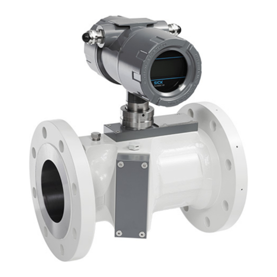
- Page 1 Title Page O P E R A T I N G I N S T R U C T I O N S FLOWSIC30 Ultrasonic Gas Flow Meter for wellhead applications Installation Operation Maintenance...
- Page 2 Risk or hazardous situation which could result in severe personal injury or death. CAUTION Hazard or unsafe practice which could result in personal injury or property damage. NOTICE Hazards which could result in property damage FLOWSIC30 · Operating Instructions · 8020999/ZQV5/V 1-3/2017-09 · © SICK Engineering GmbH...
- Page 3 IECEx scheme. Important technical information for this product Important information on electric or electronic func- tions Nice to know Supplementary information Link referring to information at another place FLOWSIC30 · Operating Instructions · 8020999/ZQV5/V 1-3/2017-09 · © SICK Engineering GmbH...
-
Page 4: Table Of Contents
Fitting the FLOWSIC30 in the pipeline ........ - Page 5 Connecting to FLOWSIC30 via FLOWgate ........
- Page 6 Wiring diagrams ............80 FLOWSIC30 · Operating Instructions · 8020999/ZQV5/V 1-3/2017-09 · © SICK Engineering GmbH...
-
Page 7: Important Information
Important Information FLOWSIC30 Important Information About this document Main hazards Intended use Responsibility of user FLOWSIC30 · Operating Instructions · 8020999/ZQV5/V 1-3/2017-09 · © SICK Engineering GmbH... -
Page 8: About This Document
Otherwise escaping gas can possibly be dangerous to health and cause injuries (e.g. poisoning, burns). WARNING: Hazards through leaks Operation in leaky condition is not allowed and possibly dangerous. ▸ Check leak tightness of equipment regularly. FLOWSIC30 · Operating Instructions · 8020999/ZQV5/V 1-3/2017-09 · © SICK Engineering GmbH... -
Page 9: Intended Use
Purpose of the device 1.3.1 The FLOWSIC30 serves measuring the gas volume, volume flow, gas temperature, gas pres- sure (optional), speed of sound and methane content of gases in pipelines. Make sure the use of the equipment complies with the technical data, information about the permitted use, assembly and installation specifications and ambient as well as opera- ting conditions. -
Page 10: Operation In Potentially Explosive Atmospheres
In these applications, also wet gas or small amount of liquids may be existent in the gas stream. However, FLOWSIC30 is a gas flow meter. All specifications of the meter apply for dry gas only. Any wet gas or liquid in the gas stream may adversely affect the uncertainty of the measured values and meter function. -
Page 11: Restrictions Of Use
▸ Do not carry out any work or repairs on the FLOWSIC30 not described in this manual. ▸ Do not remove, add or modify any components to or on the FLOWSIC30 unless described and specified in the official manufacturer information. - Page 12 Important Information FLOWSIC30 · Operating Instructions · 8020999/ZQV5/V 1-3/2017-09 · © SICK Engineering GmbH...
-
Page 13: Product Description
Product Description FLOWSIC30 Product Description Functional principle Volume conversion (option) System overview Interfaces Operating software FLOWgate FLOWSIC30 · Operating Instructions · 8020999/ZQV5/V 1-3/2017-09 · © SICK Engineering GmbH... -
Page 14: Functional Principle
Product Description Functional principle 2. 1 The FLOWSIC30 works according to the principle of ultrasonic transit time difference mea- surement. Measured signal travel times t and t are defined by the current sound and flow velocity of the gas. Gas velocity v is determined from the difference between the signal travel times. Therefore changes in the sound velocity caused by pressure or temperature fluctuations do not affect the calculated gas flow rate with this method of measurement. -
Page 15: Determining The Sound Velocity
-10 °C < T < 85 °C 1 bar (a) < p < 20 bar (a) The output value is without unit and refers to 1, uncertainty < 0.5 %. FLOWSIC30 · Operating Instructions · 8020999/ZQV5/V 1-3/2017-09 · © SICK Engineering GmbH... -
Page 16: Volume Conversion (Option)
FLOWSIC30. Prerequisites for volume conversion ● Actual process pressure is fed into FLOWSIC30 by one of the methods below: – The process pressure is set to a fix value in FLOWSIC30. – The process pressure is read in from an external HART ®... -
Page 17: Energy Flow Rate (Option)
● Fully configured volume conversion (option), → p. 16, §2.2.5 ● Heating value set by user via HART or RS485 (option) ● Heating value and volume conversion need to reference to the same temperature and pressure conditions FLOWSIC30 · Operating Instructions · 8020999/ZQV5/V 1-3/2017-09 · © SICK Engineering GmbH... -
Page 18: System Overview
System overview 2. 3 Ultrasonic gas flow meter FLOWSIC30 is designed for use in natural gas production applica- tions for gases such as coal bed methane. The dual-path meter comes with a robust car- bon steel meter body and full-titanium transducers. The ultrasonic measurement technol- ogy has no moving parts and is virtually maintenance free. -
Page 19: Interfaces
Product Description Interfaces 2 . 4 As a standard, FLOWSIC30 comes with loop-powered 4..20 mA output. The current loop ® supports HART compatible digital communication for setup and diagnosis of the meter. The interface can be used also to transmit additional measurement data. Optionally, FLOW- SIC30 can be ordered with an additional Modbus RS485 interface. -
Page 20: Rs485 Interface (Passive, Option)
The liquid detection uses real-time monitoring of multiple diagnostic parameters of the FLOWSIC30 in order to identify wet gas conditions (liquids in the gas stream such as liquid hydrocarbons, water and oil). Liquids in the gas stream are usually undesired in the gas production process and may require appropriate actions such as process optimization or consideration for meter readings. -
Page 21: Data Processing In Flowsic30
Data processing in FLOWSIC30 2 . 6 Event logbook 2.6.1 The FLOWSIC30 stores events and parameter changes in the event logbook. All events are saved with time stamp, user logged on and totalizer reading. The event logbook can be accessed via HART ®... -
Page 22: Operating Software Flowgate
● About 100 MB free disk capacity (without .NET framework) ● USB- or serial interface ● Recommended minimum screen resolution: 1024 x 768 pixel, optimal screen resolu- tion: 1368 x 768 pixel ● Microsoft .NET framework 4.0 FLOWSIC30 · Operating Instructions · 8020999/ZQV5/V 1-3/2017-09 · © SICK Engineering GmbH... -
Page 23: Overview
2 Counter readers 3 Meter status 4 Menu navigation For detailed information on the FLOWgate operating software, please refer to „FLOWgate Software Manual“ provided on the product CD. FLOWSIC30 · Operating Instructions · 8020999/ZQV5/V 1-3/2017-09 · © SICK Engineering GmbH... - Page 24 Product Description FLOWSIC30 · Operating Instructions · 8020999/ZQV5/V 1-3/2017-09 · © SICK Engineering GmbH...
-
Page 25: Installation
Installation FLOWSIC30 Installation Hazards during installation General information Mechanical Installation Electrical Installation FLOWSIC30 · Operating Instructions · 8020999/ZQV5/V 1-3/2017-09 · © SICK Engineering GmbH... -
Page 26: Hazards During Installation
Observe and comply with regulations of the plant operator. ▸ Meticulously check completed work. Ensure leak tightness and strength. Otherwise hazards are possible and safe operation is not ensured. FLOWSIC30 · Operating Instructions · 8020999/ZQV5/V 1-3/2017-09 · © SICK Engineering GmbH... -
Page 27: General Information
Inspect for damage when unpacking the device. ▸ Document any damage found and report this to the manufacturer. Do not put the FLOWSIC30 into operation if you notice any damage! ▸ Check the scope of delivery for completeness. The standard scope of delivery comprises: ●... -
Page 28: Mechanical Installation
Horizontal, electronics up Vertical Horizontal, electronics down Horizontal, electronics at side Horizontal position of ultrasonic sensors must not deviate by more than ±3° Only for dry gas FLOWSIC30 · Operating Instructions · 8020999/ZQV5/V 1-3/2017-09 · © SICK Engineering GmbH... -
Page 29: Inlet And Outlet Piping
Installation Inlet and outlet piping 3.3.3 FLOWSIC30 should be installed upstream of piping equipment such as valves, pumps, tees or elbows if possible. Fig. 8 Installation instructions ≥ 10 DN FLOWSIC30 ≥ 3 DN In order to achieve the specified meter uncertainty, ensure 10D of straight inlet and 3D of straight outlet pipe length as a minimum. -
Page 30: Fitting The Flowsic30 In The Pipeline
The device signals a malfunction when the FLOWSIC30 is installed against the prescribed flow direction. 1 Position the FLOWSIC30 at the desired location of the pipeline using the lifting gear. Only use the lifting eyes provided to lift and transport the device. If lifting straps are used, wrap them around the meter body. -
Page 31: Sun Shade For Electronics (Option)
Remove the sun shade before any work on the meter electronics. Fig. 10 Overview 1 Sun shade 4 Hex nuts 2 Notches for cables 5 Pipe clamp 3 Supporting plate 6 Connection bracket FLOWSIC30 · Operating Instructions · 8020999/ZQV5/V 1-3/2017-09 · © SICK Engineering GmbH... - Page 32 2 Position the connection bracket on the pipe clamp. 3 Slide the sun shade into the connection bracket and attach it to the pipe clamp. 4 Secure the sun shade with the hex nuts. FLOWSIC30 · Operating Instructions · 8020999/ZQV5/V 1-3/2017-09 · © SICK Engineering GmbH...
-
Page 33: Electrical Installation
Wiring work (routing and connecting the power supply and signal cables), which is necessary when installing the FLOWSIC30, is not included in the scope of delivery. The mechanical installation described in Section → 3.3 must be completed first. Comply with the minimum cable specification requirements set out in Section →... - Page 34 18…30 VDC ® Fig. 12 Intrinsically safe installation, HART + Modbus RS485 output 18…30 VDC RS485 A RS485 B 7 RS485 A 8 RS485 B 4 5…16 VDC FLOWSIC30 · Operating Instructions · 8020999/ZQV5/V 1-3/2017-09 · © SICK Engineering GmbH...
- Page 35 Non-intrinsically safe installation, HART + Modbus RS485 output 4…20 mA 18…30 VDC 7 RS485 A RS485 A 8 RS485 B RS485 B RS485 + 4 5…16 VDC RS485 - FLOWSIC30 · Operating Instructions · 8020999/ZQV5/V 1-3/2017-09 · © SICK Engineering GmbH...
-
Page 36: Cable Specifications
Do not open the window cover when an explosive atmosphere is present. NOTICE: Incorrect cabling may cause failure of the FLOWSIC30. This will invalidate warranty claims. The manufacturer assumes no liability for consequential damage. FLOWSIC30 · Operating Instructions · 8020999/ZQV5/V 1-3/2017-09 · © SICK Engineering GmbH... -
Page 37: Maximum Resistance For Analog Loop
Maximum resistance: 0 … 500 Ω (depending on power supply voltage) In order to ensure sufficient voltage at FLOWSIC30, the maximum loop resistance [Rb] in relation to the power supply voltage [US] must be considered. The operating range of the FLOWSIC30 is given in →... -
Page 38: Terminal Compartment On The Spu
360 nF 0.14 mH Read peration nstructions before installation! 4085749 NOTICE: Potential equalization PE: Potential Equalization terminals must be connected to earth ground. IEC 60079-14 must be considered. FLOWSIC30 · Operating Instructions · 8020999/ZQV5/V 1-3/2017-09 · © SICK Engineering GmbH... -
Page 39: Operating The Flowsic30
Requirements for use in hazardous areas with potentially explosive atmospheres 3.4.6 Intended use The FLOWSIC30 is suitable for use in hazardous areas classified as Zone 1 and Zone 2. Certification in accordance with ATEX II 2G Ex d e ia [ia] IIC T4 Gb (optional IIB or IIA) Permitted ambient temperature range: -25°C to +60°C for 4"... - Page 40 The ambient temperature must be within the range specified at the SPU type plate. Once the FLOWSIC30 is installed in the pipeline, the meter body becomes a part of the pipeline. The wall of the pipeline and the meter body is then deemed a zone-separating barrier.
- Page 41 – The meter body and the electronic housing must be connected to the potential equalization. – Where the FLOWSIC30 is installed in a grounded metal duct, no additional grounding is required for the meter body. The electronics housing must nevertheless be separately grounded.
- Page 42 The terminal compartment of the FLOWSIC30 complies with the requirements of EN/IEC 60079-7 and IEC60079-11. The FLOWSIC30 provides non-intrinsically safe wiring as well as intrinsically safe wiring with the interconnected associated equipment in the following manner: 1 Power supply connection and all other field connections as non-intrinsically safe wiring...
- Page 43 ● If the meter body is thermally insulated, the insulation thickness must not exceed 50 mm. The SPU housing must not be insulated. ● The standard paint of the FLOWSIC30 meter body consists of a double layer: Epoxy and Acrylic RAL9002. This combination is the ideal protection of the meter body against corrosion.
-
Page 44: Power Supply
Li = 0.07 mH 4.5V... 16 Vdc 16.8 V 15 V 10 mA 250 mA 500 mA 1.1 W RS 485 360 nF 0.14 mH Read peration nstructions before installation! 4085749 FLOWSIC30 · Operating Instructions · 8020999/ZQV5/V 1-3/2017-09 · © SICK Engineering GmbH... -
Page 45: Commissioning And Operation
Commissioning and Operation FLOWSIC30 Commissioning and Operation General Notes ® Commissioning via HART Commissioning with FLOWgate Software FLOWSIC30 · Operating Instructions · 8020999/ZQV5/V 1-3/2017-09 · © SICK Engineering GmbH... -
Page 46: General Notes
Commissioning and Operation General Notes 4. 1 Communication to the FLOWSIC30 meter can be established via the following options: ▸ HART ® communication via the current loop and with Field Communicator ▸ Service interface, located in the front of the SPU. This requires opening of the front cover. -
Page 47: Commissioning Via Hart
Commissioning via HART 4 . 2 Required tools and accessories 4.2.1 ● Field Communicator with .dd-file of the FLOWSIC30 (provided on the product CD) Establish the connection to FLOWSIC30 4.2.2 ® In order to start the commissioning procedure via HART , proceed as follows: ®... -
Page 48: Meter Installation
1 “1 Device setup” > “3 Setup” > “4 HART/Loop current” > “Dyn. Var. Assign.” 2 Chose the corresponding variable (e.g. 1 PV) and select from the list 3 Press ENTER 4 Press SEND to write the value to the meter FLOWSIC30 · Operating Instructions · 8020999/ZQV5/V 1-3/2017-09 · © SICK Engineering GmbH... -
Page 49: Analog Out
1 “1 Device setup” > “3 Setup” > “4 HART/Loop current” > “8 PV Analog damp” 2 Insert the damping value (default is 1 s) 3 Press ENTER 4 Press SEND to write the value to the meter FLOWSIC30 · Operating Instructions · 8020999/ZQV5/V 1-3/2017-09 · © SICK Engineering GmbH... -
Page 50: Electronic Volume Conversion
1 "1 Device setup" > "3 Setup" > "Volume Correction" > "2 Ref. Conditions" 2 Chose the appropriate reference 3 Press ENTER 4 Press SEND to write the value to the meter FLOWSIC30 · Operating Instructions · 8020999/ZQV5/V 1-3/2017-09 · © SICK Engineering GmbH... - Page 51 Path 2 0.50 % 0:0:1:5 0:0:1:7 Path VOS Loop Current Path 1 400.00 m/s PV Loop Current 4.00 mA Path 2 400.00 m/s PV % rnge 0.01 % FLOWSIC30 · Operating Instructions · 8020999/ZQV5/V 1-3/2017-09 · © SICK Engineering GmbH...
- Page 52 0:0:2:0:0 Dyn. Var. Assign. 0:0:2:8 PV is “Flow a.c.” Events SV is “Pressure” Event Count TV is “Temperature” Clear Event Log 4V is “Methane Content” Clear Smry. Status FLOWSIC30 · Operating Instructions · 8020999/ZQV5/V 1-3/2017-09 · © SICK Engineering GmbH...
- Page 53 0:0:4 Hotkey Menu Device Status OK / WRN / ERR Flow a.c. 1000.00 Cum/h Pressure 5.000 bar Temperature 20.0 degC 40.00 m/s 400.00 m/s Measure valid Liquid detected FLOWSIC30 · Operating Instructions · 8020999/ZQV5/V 1-3/2017-09 · © SICK Engineering GmbH...
-
Page 54: Commissioning With Flowgate Software
For detailed information, please refer to the FLOWgate software manual. 1 Install FLOWgate on a laptop/PC. 2 Connect the FLOWSIC30 to this laptop/PC using the service adapter, → p. 55, §4.3.3. 3 Start FLOWgate, either by selecting the “FLOWgate” entry in the program group “SICK”... -
Page 55: Connecting The Flowsic30 With A Laptop Or Pc
2 inside the housing at risk (e. g. through ingress of conductive dust or moisture). 1 Release the cover lock. 2 Unscrew the window cover. 3 Insert the jack plug of the service adapter. FLOWSIC30 · Operating Instructions · 8020999/ZQV5/V 1-3/2017-09 · © SICK Engineering GmbH... -
Page 56: Closing The Flowsic30
Commissioning and Operation 4 Connect the service adapter and laptop or PC with the USB cable. 5 Establish a connection to the device. 6 After completion of work, close the FLOWSIC30 properly,→ p. 56, §4.3.4. Closing the FLOWSIC30 4.3.4 1 Check the seal on the signal proces- sing unit adapter. -
Page 57: Commissioning Assistant
▸ Establish an online connection between FLOWSIC30 and FLOWgate software. ▸ Log-in as user level “Service“ (password will be provided by your local SICK representa- tive). ▸ Expand the menu navigation on the right border of the application window. Click on "Commissioning"... -
Page 58: Identification
The “Identification” view provides information on the Serial Number of the device and the firmware CRC and version used on it. Furthermore, it enables an authorized user or admin- istrator to define an identifier/tag for the device. FLOWSIC30 · Operating Instructions · 8020999/ZQV5/V 1-3/2017-09 · © SICK Engineering GmbH... -
Page 59: System/User
After having applied changes as an authorized user or higher, proceed as follows: 1 Click “Write to Device” to update the meter with the new information 2 Click “Close” to return to the “Parameter Modification” view FLOWSIC30 · Operating Instructions · 8020999/ZQV5/V 1-3/2017-09 · © SICK Engineering GmbH... -
Page 60: Analog Output
The analog signal can represent a variety of different output value sources (→ Fig. 32): Fig. 32 List of output value sources To adapt the FLOWSIC30 to the different application conditions, the analog output has to be configured. The adjustment of the analog output requires the change of various param- eters. -
Page 61: Communication
HART ® variables (PV, SV, TV, QV) to the desired parameters. ® Fig. 36 HART settings FLOWSIC30 · Operating Instructions · 8020999/ZQV5/V 1-3/2017-09 · © SICK Engineering GmbH... -
Page 62: Pressure/Temperature Sensors
After having applied changes, proceed as follows: 1 Press “Write to Device” to update the meter with the new information 2 Click on “Close” to return to the “Parameter Modification” view FLOWSIC30 · Operating Instructions · 8020999/ZQV5/V 1-3/2017-09 · © SICK Engineering GmbH... -
Page 63: Installation
1 Press “Write to Device” to update the meter with the new information 2 Click on “Close” to return to the “Parameter Modification” view NOTICE: The Liquid Indicator is automatically disabled when changing the meter orientation from horizontal to vertical. FLOWSIC30 · Operating Instructions · 8020999/ZQV5/V 1-3/2017-09 · © SICK Engineering GmbH... -
Page 64: Electronic Volume Conversion
4.3.6.9 ▸ First write the date to the device. ▸ SICK recommends creating a Parameter report and archiving the report with the deliv- ery documentation. ▸ Log out from user level “Service“. For further actions log in with user levels up to “Authorized User“. -
Page 65: Maintenance And Repair
Maintenance and Repair FLOWSIC30 Maintenance and Repair Routine checks Repair FLOWSIC30 · Operating Instructions · 8020999/ZQV5/V 1-3/2017-09 · © SICK Engineering GmbH... -
Page 66: Routine Checks
Checking the meter health 5.1.2 The FLOWSIC30 provides the user with further details on alarms, warnings and status infor- mation in the following manner: ● The LCD display indicates active system alarms and warnings. If a current error or warn- ing is active, a corresponding message will be displayed providing further information on the event. -
Page 67: Repair
Repair 5 . 2 Any repair work on the measuring system may be carried out by the SICK service or by spe- cially trained persons only. The training is provided by the manufacturer. The successfully completed SICK service training must be proved by a certificate. - Page 68 Maintenance and Repair FLOWSIC30 · Operating Instructions · 8020999/ZQV5/V 1-3/2017-09 · © SICK Engineering GmbH...
-
Page 69: Decommissioning
Decommissioning FLOWSIC30 Decommissioning Return delivery Disposal Information FLOWSIC30 · Operating Instructions · 8020999/ZQV5/V 1-3/2017-09 · © SICK Engineering GmbH... -
Page 70: Return Delivery
Contact 6.1.1 Contact your local SICK representative for assistance. Clearance certificate 6.1.2 A clearcance certificate will be provided by your local SICK representative, if necessary. Packaging 6.1.3 Make sure, the FLOWSIC30 cannot be damaged during transport. Disposal Information 6. 2 Materials 6.2.1... -
Page 71: Troubleshooting
Troubleshooting FLOWSIC30 Troubleshooting General troubleshooting System alarms and warnings Checking the meter values page via FLOWgate Creating a diagnosis session FLOWSIC30 · Operating Instructions · 8020999/ZQV5/V 1-3/2017-09 · © SICK Engineering GmbH... -
Page 72: General Troubleshooting
Volume counter checksum error E-3002 Firmware checksum error E-3003 Parameter checksum error E-3004 Logs checksum error E-3005 Date/time invalid E-3010 Flow performance failure E-3011 Pressure out of range E-3012 Reverse flow FLOWSIC30 · Operating Instructions · 8020999/ZQV5/V 1-3/2017-09 · © SICK Engineering GmbH... -
Page 73: Checking The Meter Values Page Via Flowgate
A diagnosis session can be started in the FLOWgate software by clicking on the following symbol in the device information bar: For detailed information, please refer to the FLOWgate user manual provided on the prod- uct CD or via the FLOWgate software. FLOWSIC30 · Operating Instructions · 8020999/ZQV5/V 1-3/2017-09 · © SICK Engineering GmbH... - Page 74 Troubleshooting FLOWSIC30 · Operating Instructions · 8020999/ZQV5/V 1-3/2017-09 · © SICK Engineering GmbH...
-
Page 75: Specifications
Specifications FLOWSIC30 Specifications Conformities and technical data Type plate Dimensional drawings FLOWSIC30 · Operating Instructions · 8020999/ZQV5/V 1-3/2017-09 · © SICK Engineering GmbH... -
Page 76: Conformities And Technical Data
● ACMA Radiocommunications Act. 1992, section 182 (RCM label) ● Qualification acc. to ASME ● IECEx: IEC 60079-0, IEC 60079-1, IEC 60079-7, IEC 60079-11 ● EN 60079-0, EN 60079-1, EN 60079-7, EN 60079-11 FLOWSIC30 · Operating Instructions · 8020999/ZQV5/V 1-3/2017-09 · © SICK Engineering GmbH... -
Page 77: Technical Data
Integrated relative pressure sensor (optional) Measuring range 0 ... 2000 kPag Measuring precision ± 0.1% of measuring range (full scale) Installation Dimensions (W x H x D) See dimensional drawings FLOWSIC30 · Operating Instructions · 8020999/ZQV5/V 1-3/2017-09 · © SICK Engineering GmbH... -
Page 78: Type Plate
Made in German y 4086242 Read Operation Instru ctions before installation! Fig. 42 Type plate on the meter body (example) FLOWSIC30 Year 2016 19,6bar@38°C DN/NPS 100/04” 18,3bar@80°C Weight 30kg 30bar test FLOWSIC30 · Operating Instructions · 8020999/ZQV5/V 1-3/2017-09 · © SICK Engineering GmbH... -
Page 79: Dimensional Drawings
= 263 / 293 [10.35 / 11.54] b = 377 / 407 [14.84 / 16.02] c = 102.3 [4.03] 3 inch: a = 290 [11.41] b = 385 [15.16] c = 77.9 [3.07] FLOWSIC30 · Operating Instructions · 8020999/ZQV5/V 1-3/2017-09 · © SICK Engineering GmbH... -
Page 80: Wiring Diagrams
The optional internal pressure and temperature sensors do not require extra device exter- nal cabling. Extra cabling is only required, if the optional RS485 or an external pressure or temperature sensor (not included in scope of delivery) is used. FLOWSIC30 · Operating Instructions · 8020999/ZQV5/V 1-3/2017-09 · © SICK Engineering GmbH... - Page 81 Specifications Fig. 46 Intrinsically-safe installation/Ex i (9239655) FLOWSIC30 · Operating Instructions · 8020999/ZQV5/V 1-3/2017-09 · © SICK Engineering GmbH...
- Page 82 Specifications Fig. 47 Intrinsically-safe installation/Ex i (9239659) FLOWSIC30 · Operating Instructions · 8020999/ZQV5/V 1-3/2017-09 · © SICK Engineering GmbH...
- Page 83 Specifications Fig. 48 Intrinsically-safe installation/Ex i RS485 (9257234) FLOWSIC30 · Operating Instructions · 8020999/ZQV5/V 1-3/2017-09 · © SICK Engineering GmbH...
- Page 84 Specifications Fig. 49 Increased safety installation/Ex e (9239656) FLOWSIC30 · Operating Instructions · 8020999/ZQV5/V 1-3/2017-09 · © SICK Engineering GmbH...
- Page 85 Specifications Fig. 50 Increased safety installation/Ex e pT (9239657) FLOWSIC30 · Operating Instructions · 8020999/ZQV5/V 1-3/2017-09 · © SICK Engineering GmbH...
- Page 86 Specifications Fig. 51 Increased safety installation/Ex e RS485 (9239658) FLOWSIC30 · Operating Instructions · 8020999/ZQV5/V 1-3/2017-09 · © SICK Engineering GmbH...
- Page 87 Specifications FLOWSIC30 · Operating Instructions · 8020999/ZQV5/V 1-3/2017-09 · © SICK Engineering GmbH...
- Page 88 E-Mail sales@sick.co.nz United Arab Emirates China Norway E-Mail sick@sick.no USA/Mexico Denmark Poland E-Mail sick@sick.dk Finland Romania Vietnam France Russia Gemany Singapore Great Britain Slovakia E-Mail mail@sick-sk.sk Hong Kong Slovenia Hungary South Africa www.sick.com SICK AG | Waldkirch | Germany | www.sick.com...
Need help?
Do you have a question about the FLOWSIC30 and is the answer not in the manual?
Questions and answers