
Subscribe to Our Youtube Channel
Related Manuals for IBASE Technology ASB200-918 Series


Summary of Contents for IBASE Technology ASB200-918 Series
- Page 1 ASB200-918 Fanless System with 3.5” Disk-Size SBC System User’s Manual Version 1.0 (October 2020)
- Page 2 No part of this publication may be reproduced, copied, stored in a retrieval system, translated into any language or transmitted in any form or by any means, electronic, mechanical, photocopying, or otherwise, without the prior written consent of IBASE Technology, Inc. (hereinafter referred to as “IBASE”).
- Page 3 Compliance This product has passed CE tests for environmental specifications and limits, in accordance with the directives of the Union European (EU). If users modify and/or install other devices in this equipment, the CE conformity declaration may no longer apply. This product has been tested and found to comply with the limits for a Class B device, pursuant to Part 15 of the FCC Rules.
- Page 4 Important Safety Information Carefully read the precautions before using the device. Environmental conditions: Lay the device horizontally on a stable and solid surface in case the device may fall, causing serious damage. Leave plenty of space around the device and do not block the openings for ventilation.
- Page 5 CAUTION Danger of explosion if internal lithium-ion battery is replaced by an incorrect type. Replace only with the same or equivalent type recommended by the manufacturer. Dispose of used batteries according to the manufacturer’s instructions. Warranty Policy IBASE standard products: 24-month (2-year) warranty from the date of shipment.
-
Page 6: Table Of Contents
Table of Contents Chapter 1 General Information ..............1 Introduction ..................... 2 Features ....................2 Packing List .................... 3 Optional Accessories ................3 Specifications ..................4 Product View ................... 6 Dimensions ..................... 8 Chapter 2 Hardware Configuration ............9 Installations ................... 10 2.1.1 HDD Installation .............. - Page 7 Chapter 3 Driver Installation ..............25 Introduction ................... 26 AMD Ryzen™ V1000 Graphics Drivers ..........26 AMD Ryzen™ R1000 Graphics Drivers..........28 HD Audio Driver Installation ..............30 LAN Driver Installation ................31 Observer ....................34 Chapter 4 BIOS Setup ................36 Introduction ...................
- Page 8 THIS PAGE IS INTENTIONALLY LEFT BLANK. viii ASB200-918 User Manual...
-
Page 9: Chapter 1 General Information
Chapter 1 General Information The information provided in this chapter includes: Features Packing List Optional Accessories Specifications Product View Dimensions... -
Page 10: Introduction
1.1 Introduction The ASB200-918 compact fanless system supports the AMD Ryzen™ Embedded V1000/R1000 SoC featuring Vega GPU for stunning 4K Ultra High-Definition resolution and driving two HDMI (2.0a) graphics display. It supports two SO-DIMM sockets supporting fast data transfers with up to 32GB DDR4-2400 memory and ECC for data integrity and flexible I/O connectivity and expansion ports. -
Page 11: Packing List
General Information 1.3 Packing List Your product package should include the items listed below. If any of the items below is missing, contact the distributor or the dealer from whom you purchased the product. ASB200-918…………………………………………………………………x 1 3-Pin Terminal Block (for power)………………………………………….x 1 ... -
Page 12: Specifications
1.5 Specifications ASB200- ASB200- ASB200- ASB200- Product Name 918-1605 918-1202 918-1606G 918-1505G Motherboard IB918F-1605 IB918F-1202 IB918F-1606G IB918F-1505G 3.5” disk-size SBC MB Form Factor System Windows 10 Operating System Linux Ubuntu / Fedora AMD Embedded V1605B V1202B R1606G R1505G Ryzen™... - Page 13 General Information I/O Interface 1 x Power button/RST/HDD/On/Off 2 x Antenna holes Front Panel I/O 1 x Audio Jack for Line-out/Line-in/Mic-in 3 x DB9 for COM#2~#4 (RS232 only) 1 x USB port 2.0/3.0 1 x 3-pin terminal block connector for external digital I/O 1x GPIO (4-in/4-out) 1 x DB9 for COM#1 (RS232/422/485), Rear Panel I/O...
-
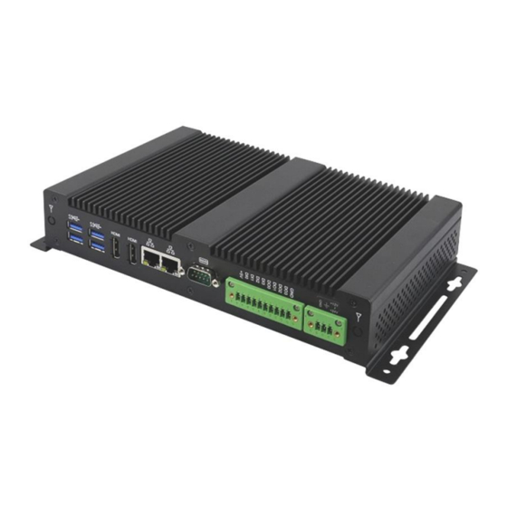
Page 14: Product View
1.6 Product View Front View No. Name No. Name Audio Jacks PWR LED Indicator (From left to right: Mic-In, Line-In, Lin-Out) USB 3.0 (ASB200-918-1605 & ASB200-918-1202 only ) HDD LED Indicator USB 2.0 (ASB200-918-1606 & ASB200-918-1505 only ) COM2 ~ COM4 Ports Power Button (COM2 ~ COM4: RS-232) Reset Button... - Page 15 General Information Rear View No. Name No. Name DC-In Power Connector HDMI Port Digital I/O Connector USB 3.0 Ports (4-In / 4-Out) COM1 2 Antenna Holes (COM1: RS-232/422/485) GbE LAN Ports Oblique View ASB200-918 User Manual...
-
Page 16: Dimensions
1.7 Dimensions Unit: mm ASB200-918 User Manual... -
Page 17: Chapter 2 Hardware Configuration
Chapter 2 Hardware Configuration The information provided in this chapter includes: Installations Information and locations of connectors... -
Page 18: Installations
2.1 Installations Before installations, you need to remove the bottom chassis cover by loosening the screws shown below. After removing the above screws, remove the bottom chassis cover. ASB200-918 User Manual... -
Page 19: Hdd Installation
Hardware Configuration 2.1.1 HDD Installation If you need to install or replace an SSD or a HDD, remove the single screw shown below to remove the tray, and then loosen the four screws. Attach the SSD / HDD and tighten these screws. Remove the single screw holding the tray. -
Page 20: Memory Installation
2.1.2 Memory Installation If you need to install or replace a memory module, perform the following steps: 1. Locate the memory slot on the board. 2. Align the key of the memory module with that on the memory slot and insert the module slantwise. -
Page 21: Wifi / 3G / 4G Antenna Installation
Hardware Configuration 2.1.4 WiFi / 3G / 4G Antenna Installation Thread the WiFi / 3G / 4G antenna cable through an antenna hole. Then fasten the antenna as shown below. Info: The diameter of the nut is around 6.35 mm (0.25”-36UNC). 2.1.5 Side Bracket Installation Install the side bracket by using the four screws supplied with the package. -
Page 22: Pinout For Com Ports, Dc Power & Digital I/O Connectors
2.1.6 Pinout for COM Ports, DC Power & Digital I/O Connectors RS232/422/485 COM Port Signal Signal DCD, Data carrier detect DSR, Data set ready RXD, Receive data RTS, Request to send TXD, Transmit data CTS, Clear to send DTR, Data terminal ready RI, Ring indicator Ground DC Power Input Connector (terminal block) -
Page 23: Setting The Jumpers
Hardware Configuration 2.2 Setting the Jumpers Set up and configure your product by using jumpers for various settings and features according to your needs and applications. Contact your supplier if you have doubts about the best configuration for your use. 2.2.1 How to Set Jumpers Jumpers are short-length conductors consisting of several metal pins with a... -
Page 24: Jumper & Connector Locations On Motherboard
2.3 Jumper & Connector Locations on Motherboard Motherboard: IB918 CPU_FAN1 Gen. Core™ / Intel ® Celeron ® Board diagram of IB918 ASB200-918 User Manual... -
Page 25: Jumpers Quick Reference
Hardware Configuration 2.4 Jumpers Quick Reference Function Connector Page CMOS Data Clearance ME Register Clearance eDP Panel Power Selection Factory Use Only 2.4.1 Clear CMOS Data (JP2) Function Pin closed Normal (default) Clear CMOS ASB200-918 User Manual... -
Page 26: Clear Me Register (Jp3)
2.4.2 Clear ME Register (JP3) Function Pin closed Normal (default) Clear ME 2.4.3 eDP Panel Power Selection (JP4) Function Pin closed 3.3V (default) ASB200-918 User Manual... -
Page 27: Connectors Quick Reference
Hardware Configuration 2.5 Connectors Quick Reference Function Connector Page eDP Connector Audio Connector SATA HDD Power Connector Front Panel Setting Connector USB 2.0 Connector Battery Connector DC Power Input Connector Digital I/O Connector COM1 RS-232/422/485 Port COM2, COM3, COM4 RS-232 Ports J15, J12, J11 -- SATA III Port CN1, CN3... -
Page 28: Edp Connector (Cn2)
2.5.1 eDP Connector (CN2) Signal Signal Ground BL_Power BL_Power Panel_VDD BL_Power Panel_VDD BL_Power Ground AUX_N AUX_P Brightness Ground Bklt_en TX0_P Ground TX0_N Ground Ground Ground TX1_P Ground TX1_N Ground Ground ASB200-918 User Manual... -
Page 29: Audio Connector (J1)
Hardware Configuration 2.5.2 Audio Connector (J1) Signal Signal Lineout_L Lineout_R JD_FRONT Ground LINEIN_L Linein_R JD_LINEIN Ground MIC_L MIC-R JD_MIC1 Ground 2.5.3 SATA HDD Power Connector (J5) Signal Signal Ground Ground +12V ASB200-918 User Manual... -
Page 30: Front Panel Connector (J6)
2.5.4 Front Panel Connector (J6) Signal Signal Ground PWR_BTN 3.3V HDD Active Ground Reset Ground J6 is utilized for system indicators to provide light indication of the computer activities and switches to change the computer status. It provides interfaces for the following functions. ... -
Page 31: Usb 2.0 Connector (J7)
Hardware Configuration 2.5.5 USB 2.0 Connector (J7) Signal Signal Ground Ground 2.5.6 Battery Connector (J10) Signal Signal Battery+ Ground ASB200-918 User Manual... -
Page 32: Dc Power Input Connector (J13)
2.5.7 DC Power Input Connector (J13) Signal Signal +9V ~ +24V Ground 2.5.8 Digital I/O Connector (J16) Signal Signal Ground OUT3 OUT1 OUT2 OUT0 ASB200-918 User Manual... -
Page 33: Chapter 3 Driver Installation
Chapter 3 Driver Installation The information provided in this chapter includes: Introduction AMD Ryzen™ V1000 Graphics Drivers AMD Ryzen™ R1000 Graphics Drivers HD Audio Driver Installation LAN Driver Installation Observer... -
Page 34: Introduction
3.1 Introduction This section describes the installation procedures for software and drivers. The contents of this section include the following: 3.2 AMD Ryzen™ V1000 Graphics Drivers 1. Insert the disk enclosed in the package. Click AMD on the left pane and then AMD Ryzen V1000 Drivers on the right pane. - Page 35 Driver Installation 3. Now click Accept and Install to proceed. 4. Click on either Express Install or Custom Install. 5. When the software driver has been installed, restart the computer for changes to take effect. ASB200-918 User Manual...
-
Page 36: Amd Ryzen™ R1000 Graphics Drivers
3.3 AMD Ryzen™ R1000 Graphics Drivers 1. Insert the disk enclosed in the package. Click AMD on the left pane and then AMD Ryzen R1000 Drivers on the right pane. 2. Click AMD Ryzen R1000 Graphics Drivers. ASB200-918 User Manual... - Page 37 Driver Installation 3. Read the software license agreement and click Accept and Install to proceed. 4. Click on either Express Install or Custom Install. 5. When the software driver has been installed, restart the computer for changes to take effect. ASB200-918 User Manual...
-
Page 38: Hd Audio Driver Installation
3.4 HD Audio Driver Installation 1. Insert the disk enclosed in the package with the board. Click AMD on the left pane and then Realtek High Definition Audio Driver on the right pane. 2. On the Welcome screen of the InstallShield Wizard, click Next. 3. -
Page 39: Lan Driver Installation
Driver Installation 3.5 LAN Driver Installation 1. Insert the disk enclosed in the package. Click LAN Card on the left pane and Intel LAN Controller Drivers on the right pane. 2. Click Intel(R) I21x Gigabit Networks Drivers. ASB200-918 User Manual... - Page 40 3. When the Welcome screen appears, click Next. 4. Choose “I accept the terms in the license agreement” and click Next. 5. Click Next after selecting the program features as shown below. ASB200-918 User Manual...
- Page 41 Driver Installation 6. On the next screen, click Install to install the program. 7. When the wizard has successfully installed the Program, restart your computer for changes to take effect. ASB200-918 User Manual...
-
Page 42: Observer
3.6 Observer 1. Insert the disk enclosed in the package with the board. Click Tools on the left pane and then Observer on the right pane. 2. Click Next when the Welcome screen appears and to continue installing the Observer on your computer. ASB200-918 User Manual... - Page 43 Driver Installation 3. The next screen shows the destination location where Observer will be installed. Click Next. 4. Setup is now ready to begin installing Observer on your computer. Click Install. 5. To complete the installation of Observer, restart the computer (click Finish) for changes to take effect.
-
Page 44: Chapter 4 Bios Setup
Chapter 4 BIOS Setup This chapter the different settings available in the AMI describes BIOS that comes with the board. The topics covered in this chapter are as follows: Main Settings Advanced Settings Chipset Settings Security Settings ... -
Page 45: Introduction
BIOS Setup 4.1 Introduction The BIOS (Basic Input/Output System) installed in the ROM of your computer system supports Intel® processors. The BIOS provides critical low-level support for standard devices such as disk drives, serial ports and parallel ports. It also provides password protection as well as special support for detailed fine-tuning of the chipset controlling the entire system. -
Page 46: Main Settings
4.3 Main Settings BIOS Setting Description Sets the date. Use the <Tab> key to switch between the System Date data elements. Set the time. Use the <Tab> key to switch between the System Time data elements. 4.4 Advanced Settings This section allows you to configure, improve your system and allows you to set up some system features according to your preference. - Page 47 BIOS Setup 4.4.1 Trusted Computing Settings BIOS Setting Description Security Enables or Disables BIOS support for security device. OS Device will now show Security Device. TCG EFI protocol and Support INT1A interface will not be available (Default: Enable) SHA-1 PCR Enable or Disable (Default: Enable) Bank SHA-256 PCR...
- Page 48 BIOS Setting Description Endorsement Enable or Disable (Default: Enable) HIerarchy Select the tCG2 spec version support. TPM2.0 UEFI TCG_1_2: the compatible mode for Win8/Win10 Spec Version TCG_2: Support new tCG2 protocol and event format for Win10 or later. (Default: TCG_2) Physical Select to tell OS to support PPI spec version 1.2 or Presence Spect...
- Page 49 BIOS Setup 4.4.2 ACPI Settings BIOS Setting Description Enable ACPI Auto Enables / Disables BIOS ACPI auto configuration. Configuration Enables / Disables the system ability to hibernate Enable Hibernation (OS/S4 Sleep State). This option may be not effective with some OS. Selects an ACPI sleep state where the system will ACPI Sleep State enter when the Suspend button is pressed.
- Page 50 4.4.4 LVDS Configuration BIOS Setting Description LVDS Control Enables / Disables the LVDS function. When enabled, LVDS Control will show the following items with their options: 1. Panel Color Depth: 18 BIT / 24 BIT 2. LVDS Channel Type: Single / Dual 3.
- Page 51 BIOS Setup ASB200-918 User Manual...
- Page 52 4.4.6 Hardware Monitor BIOS Setting Description CPU Fan Smart Enables / Disables the CPU smart fan feature. Fan Control Temperatures / The values are read-only values as monitored by the Fan Speed / system and show the PC health status. Voltages CPU Shutdown Enables / Disables the CPU shutdown temperature...
- Page 53 BIOS Setup 4.4.7 CPU Configuration BIOS Setting Description Node 0 Displays the memory information related to Node 0. Information 4.4.8 AMI Graphic Output Protocol Policy BIOS Setting Description Output Select Allows you to select an output interface. ASB200-918 User Manual...
- Page 54 4.4.9 USB Configuration BIOS Setting Description Enables Legacy USB support. Auto disables legacy support if there is no USB Legacy USB device connected. Support Disable keeps USB devices available only for EFI applications. This is a workaround for OSes without XHCI hand-off support.
- Page 55 BIOS Setup 4.4.10 CSM Configuration BIOS Setting Description CSM Support Enables / Disables CSM support. Controls the execution of UEFI and Legacy PXE OpROM. Network Options: Do not launch UEFI / Legacy 4.4.11 NVMe Configuration 4.4.12 Network Stack Configuration BIOS Setting Description Network Stack Enables / Disables UEFI Network Stack.
- Page 56 4.4.13 AMD CBS BIOS Setting Description NB Common This is for the NB configuration for IOMMU settings Options and system configuration. FCH Common Here you can set the AC loss control method with Options options of: Always Off / Always On ASB200-918 User Manual...
-
Page 57: Chipset Settings
BIOS Setup 4.5 Chipset Settings 4.5.1 SB USB Configuration BIOS Setting Description SB USB Configuration Options for SB USB Configuration. 4.5.1.1. XHCI Ports BIOS Setting Description XHCI0 & XHCI1 Enables / Disables the XHCI0 & XHCI1 ports Ports (XHCI/EMCI). ASB200-918 User Manual... -
Page 58: Security Settings
4.6 Security Settings BIOS Setting Description Administrator Sets an administrator password for the setup utility. Password User Password Sets a user password. Single Thread Indirect Branch Predictor (STIBP) is a method to mitigate indirect branch target injection STIBP Status attacks on AMD products. Options: Disabled, Enabled Secure Boot feature is Active if Secure Boot is enabled. -
Page 59: Boot Settings
BIOS Setup 4.7 Boot Settings BIOS Setting Description Number of seconds to wait for setup activation Setup Prompt Timeout key. 65535(0xFFFF) means indefinite waiting. Bootup NumLock State Selects the keyboard NumLock state. Quiet Boot Enables / Disables Quiet Boot option. Boot mode select Selects a Boot mode, Legacy / UEFI. -
Page 60: Save & Exit
4.8 Save & Exit BIOS Setting Description Save Changes and Exit Exits system setup after saving the changes. Exits system setup without saving any Discard Changes and Exit changes. Save Changes and Reset Resets the system after saving the changes. Discard Changes and Resets system setup without saving any Reset... -
Page 61: Appendix
Appendix This section provides the mapping addresses of peripheral devices and the sample code of watchdog timer configuration. I/O Port Address Map Interrupt Request Lines (IRQ) Digital I/O Sample Code Watchdog Timer Configuration... -
Page 62: I/O Port Address Map
A. I/O Port Address Map Each peripheral device in the system is assigned a set of I/O port addresses which also becomes the identity of the device. The following table lists the I/O port addresses used. Address Device Description 0x00000A00-0x00000A0F Motherboard resources 0x00000A10-0x00000A1F Motherboard resources... - Page 63 Appendix Address Device Description 0x00000090-0x0000009F Motherboard resources 0x000000A2-0x000000BF Motherboard resources 0x000000B1-0x000000B1 Motherboard resources 0x000000E0-0x000000EF Motherboard resources 0x000004D0-0x000004D1 Motherboard resources 0x0000040B-0x0000040B Motherboard resources 0x000004D6-0x000004D6 Motherboard resources 0x00000C00-0x00000C01 Motherboard resources 0x00000C14-0x00000C14 Motherboard resources 0x00000C50-0x00000C51 Motherboard resources 0x00000C52-0x00000C52 Motherboard resources 0x00000C6C-0x00000C6C Motherboard resources 0x00000C6F-0x00000C6F Motherboard resources 0x00000CD0-0x00000CD1...
-
Page 64: Interrupt Request Lines (Irq)
B. Interrupt Request Lines (IRQ) Peripheral devices use interrupt request lines to notify CPU for the service required. The following table shows the IRQ used by the devices on board. Level Function IRQ 4294967292 PCI Express Root Port IRQ 0 High precision event timer IRQ 0 System timer... -
Page 65: Digital I/O Sample Code
Appendix E. Digital I/O Sample Code 1. DIO Sample Code: The file F81846.cpp //====================================================================== // THIS CODE AND INFORMATION IS PROVIDED "AS IS" WITHOUT WARRANTY OF ANY // KIND, EITHER EXPRESSED OR IMPLIED, INCLUDING BUT NOT LIMITED TO THE // IMPLIED WARRANTIES OF MERCHANTABILITY AND/OR FITNESS FOR A PARTICULAR // PURPOSE. - Page 66 //====================================================================== void Lock_F81846 (void) outportb(F81846_INDEX_PORT, F81846_LOCK); //====================================================================== void Set_F81846_LD( unsigned char LD) Unlock_F81846(); outportb(F81846_INDEX_PORT, F81846_REG_LD); outportb(F81846_DATA_PORT, LD); Lock_F81846(); //====================================================================== void Set_F81846_Reg( unsigned char REG, unsigned char DATA) Unlock_F81846(); outportb(F81846_INDEX_PORT, REG); outportb(F81846_DATA_PORT, DATA); Lock_F81846(); //====================================================================== unsigned char Get_F81846_Reg(unsigned char REG) unsigned char Result; Unlock_F81846();...
- Page 67 Appendix 2. DIO Sample Code: The file F81846.h //====================================================================== // THIS CODE AND INFORMATION IS PROVIDED "AS IS" WITHOUT WARRANTY OF ANY // KIND, EITHER EXPRESSED OR IMPLIED, INCLUDING BUT NOT LIMITED TO THE // IMPLIED WARRANTIES OF MERCHANTABILITY AND/OR FITNESS FOR A PARTICULAR // PURPOSE.
- Page 68 3. DIO Sample Code: The file MAIN.CPP //--------------------------------------------------------------------------- // THIS CODE AND INFORMATION IS PROVIDED "AS IS" WITHOUT WARRANTY OF ANY // KIND, EITHER EXPRESSED OR IMPLIED, INCLUDING BUT NOT LIMITED TO THE // IMPLIED WARRANTIES OF MERCHANTABILITY AND/OR FITNESS FOR A PARTICULAR // PURPOSE.
-
Page 69: Watchdog Timer Configuration
Appendix F. Watchdog Timer Configuration The Watchdog Timer (WDT) is used to generate a variety of output signals after a user programmable count. The WDT is suitable for use in the prevention of system lock-up, such as when software becomes trapped in a deadlock. - Page 70 2. Sample Code: The file MAIN.CPP //--------------------------------------------------------------------------- // THIS CODE AND INFORMATION IS PROVIDED "AS IS" WITHOUT WARRANTY OF ANY // KIND, EITHER EXPRESSED OR IMPLIED, INCLUDING BUT NOT LIMITED TO THE // IMPLIED WARRANTIES OF MERCHANTABILITY AND/OR FITNESS FOR A PARTICULAR // PURPOSE.
- Page 71 Appendix Set_NCT6116D_LD(0x08); //switch to logic device bBuf = Get_NCT6116D_Reg(0x30); bBuf &= (~0x01); Set_NCT6116D_Reg(0x30, bBuf); //Enable WDTO //--------------------------------------------------------------------------- void WDTEnable(unsigned char NewInterval) unsigned char bBuf; Set_NCT6116D_LD(0x08); //switch to logic device Set_NCT6116D_Reg(0x30, 0x01); //enable timer bBuf = Get_NCT6116D_Reg(0xF0); bBuf &= (~0x08); Set_NCT6116D_Reg(0xF0, bBuf); //count mode is second Set_NCT6116D_Reg(0xF1, NewInterval);...
- Page 72 3. Sample Code: The file NCT6116D.CPP //--------------------------------------------------------------------------- // THIS CODE AND INFORMATION IS PROVIDED "AS IS" WITHOUT WARRANTY OF ANY // KIND, EITHER EXPRESSED OR IMPLIED, INCLUDING BUT NOT LIMITED TO THE // IMPLIED WARRANTIES OF MERCHANTABILITY AND/OR FITNESS FOR A PARTICULAR // PURPOSE.
- Page 73 Appendix void Lock_NCT6116D (void) outportb(NCT6116D_INDEX_PORT, NCT6116D_LOCK); //--------------------------------------------------------------------------- void Set_NCT6116D_LD( unsigned char LD) Unlock_NCT6116D(); outportb(NCT6116D_INDEX_PORT, NCT6116D_REG_LD); outportb(NCT6116D_DATA_PORT, LD); Lock_NCT6116D(); //--------------------------------------------------------------------------- void Set_NCT6116D_Reg( unsigned char REG, unsigned char DATA) Unlock_NCT6116D(); outportb(NCT6116D_INDEX_PORT, REG); outportb(NCT6116D_DATA_PORT, DATA); Lock_NCT6116D(); //--------------------------------------------------------------------------- unsigned char Get_NCT6116D_Reg(unsigned char REG) unsigned char Result; Unlock_NCT6116D();...
- Page 74 //--------------------------------------------------------------------------- // THIS CODE AND INFORMATION IS PROVIDED "AS IS" WITHOUT WARRANTY OF ANY // KIND, EITHER EXPRESSED OR IMPLIED, INCLUDING BUT NOT LIMITED TO THE // IMPLIED WARRANTIES OF MERCHANTABILITY AND/OR FITNESS FOR A PARTICULAR // PURPOSE. //--------------------------------------------------------------------------- #include "F81846.H" #include <dos.h>...
- Page 75 Appendix outportb(F81846_INDEX_PORT, F81846_REG_LD); outportb(F81846_DATA_PORT, LD); Lock_F81846(); //--------------------------------------------------------------------------- void Set_F81846_Reg( unsigned char REG, unsigned char DATA) Unlock_F81846(); outportb(F81846_INDEX_PORT, REG); outportb(F81846_DATA_PORT, DATA); Lock_F81846(); //--------------------------------------------------------------------------- unsigned char Get_F81846_Reg(unsigned char REG) unsigned char Result; Unlock_F81846(); outportb(F81846_INDEX_PORT, REG); Result = inportb(F81846_DATA_PORT); Lock_F81846(); return Result; //--------------------------------------------------------------------------- //--------------------------------------------------------------------------- // THIS CODE AND INFORMATION IS PROVIDED "AS IS"...
Need help?
Do you have a question about the ASB200-918 Series and is the answer not in the manual?
Questions and answers