
Related Manuals for EPOX M762A Series


Summary of Contents for EPOX M762A Series
- Page 1 M762A Series (Industrial Board) NSTALLATION UIDE Installation Guide Revision A.0...
- Page 2 600C002762AA0...
- Page 4 COPYRIGHT © All rights reserved. The information contained in this guide has been validated and reviewed for accuracy. No patent liability is assumed with respect to the use of the information contained herein. While every precaution has been taken in the preparation of this guide, the Manufacturer assumes no responsibility for errors or omissions.
-
Page 5: Table Of Contents
Unpacking M762A Series Description Features 1.3.1 Chipset Features 1.3.2 Ultra ATA/66/100 1.3.3 Hardware Monitoring 1.3.4 I/O Shield Connector 1.3.5 Power-On/Off 1.3.6 M762A Series Overview 1.3.7 System Block Diagram Specifications ECTION NSTALLATIONS System Installation 2.1.1 CPU Installation 2.1.2 Memory Module Installation 2.1.3 Setting Jumper and DIP Switches... - Page 6 ONTENTS BIOS S ECTION WARD ETUP BIOS Instructions Main Menu Standard CMOS Features IDE Adapters Advanced BIOS Features Advanced Chipset Features Integrated Peripherals Power Management Setup PnP/PCI Configurations 3.10 PC Health Status 3.11 Frequency/Voltage Control 3.12 Load Fail-Safe Default 3.13 Load Optimized Defaults 3.14 Supervisor/User Password Setting 3.15 Exit Selecting ECTION...
-
Page 8: Section 1 Introduction
SECTION NTRODUCTION Unpacking M762A Series 1. Take out the M762A series unit from the carton box, check if the unit is properly secure in the plastic bag. 2. Check the contents of the carton box: Industrial Board Installation Guide ... -
Page 9: Description
Introduction Description The M762A series combines the high performance and exceptional value of AMD-760™MPX chipset with a full-featured, new generation, dual processors server board. The AMD-760™MPX chipset is a high performance dual processor core logic solution for AMD Athlon™ MP processors. -
Page 10: Ultra Ata/66/100
Introduction Together, these components provide a powerful solution for high-end- Desktop, Workstation and Server class platforms. 1.3.2 Ultra ATA/66/100 The AMD ® 768™ peripheral bus controller provides two channel Ultra ATA- 33/66/100 Bus Master IDE controller, that support Ultra ATA-33/66/100 protocols, perfect for such demanding applications as real-time video, multimedia, and high performance operating system. -
Page 11: Power-On/Off
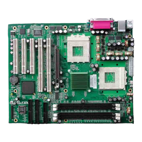
M/B onboard circuit controller) that can be controlled by the operating ® ® system such as Windows 95/98/SE/ME or Windows 2000. 1.3.6 M762A Series Overview Function / Model M762A Chipset AMD-760™MPX (762+768) LCD Function VGA Function SCSI Function ... -
Page 12: System Block Diagram
Introduction 1.3.7 System Block Diagram Figure 2: System Block Diagram... -
Page 13: Specifications
Introduction Specifications Processor: - Dual AMD ® Athlon™ MP processor - System bus frequency at 200/266 MHz Chipset: - AMD-760™MPX Chipsets - AMD-762™ System Controller (Northbridge) - AMD-768™ Peripheral Bus Controller (Southbridge) DRAM Module: - 184pin DDR Memory - x 4 for PC2100 DDR memory sockets - Support DDR up to 3.5GB ... - Page 14 Introduction USB Ports: - USB connector x 4 (2 for Opt. by cable) BIOS: - Award Plug & Play BIOS Extended Function: - Supports exclusive USDM (Unified System Diagnostic Manager) and Hardware Monitoring Function by W83627HF-AW - Supports Wake-On-LAN Function ...
-
Page 15: Section 2 Installations
SECTION NSTALLATIONS System Installation 2.1.1 CPU Installation Carefully follow the steps below in order to install the CPU: 1. Check and confirm that the jumpers are correctly set for the CPU you are going to install (figure 3). 2. Lift the releasing lever of the Socket 462. 3. -
Page 16: Memory Module Installation
Installations Removing a CPU: 1. Before removing the CPU, turn off the M762A series power; then wait for about 20 minutes until the heat radiation plate of the cooling fan and the CPU cools down. 2. To remove the CPU, lift the releasing lever of the Socket 462. - Page 17 2. Do not touch the connector of the DIMM. Dirt residue may cause a malfunction. 3. Hold the DIMM with its notch to the front side of the M762A series and insert it completely into the socket. A DIMM should be inserted into the inner socket first.
-
Page 18: Setting Jumper And Dip Switches
Installations 2.1.3 Setting Jumpers and DIP Switches There are jumpers and DIP-switches on the system board of the M762A series. You can set the jumpers to make the necessary operations. Figure 6: Jumper Connector For any three-pin jumpers (figure 6), the jumper setting is 1-2 when the jumper connects pins 1 and 2. -
Page 19: Board Layout
Installations Board Layout Jumper & Connector Location... -
Page 20: Jumper Setting
Installations Jumper Setting Table for Jumper Location Description: Use the information in the following table to change the jumpers and the switches. Jumpers Functions JP2 & JP3 CPU Frequency Setting Select FSB Setting Select Clear CMOS Setting Select Watchdog Timer Setting Select... - Page 21 Installations In order to set up the correct configuration, here is the description about how to set the jumpers to enable/disable or change functions. All jumpers’ location please refer to jumper location diagram. CPU Frequency Setting Select: JP2 & JP3 Function 100 MHz (Default) 66 MHz...
- Page 22 Installations Clear CMOS Setting Select: JP5 Function Normal (Default) Clear CMOS Location: Watchdog Timer Setting Select: JP6 Function Reset System (Default) Location:...
-
Page 23: Connector's Description
Installations Connector’s Description Connector Location... - Page 24 Installations Table for Connector’s Location Description: Use the information in the following table to change the connector. Connectors Functions COM1 RS-232 Serial Port Connector Parallel Port Connector COM2 RS-232 Serial Port Connector ® LAN1 (Intel 82559) RJ45 & USB 1/2 Connector PS/2 Keyboard &...
- Page 25 Installations COM1 RS-232 Serial Port Connector (D-Sub 9-pin Male): CN1 Pin # Assignment Pin # Assignment DCD (Data Carrier Detect) DSR (Data Set Ready) RXD (Receive Data) RTS (Request to Send) TXD (Transmit Data) CTS (Clear to Send) DTR (Data Terminal Ready) RI (Ring Indicator) DCD (Data Carrier Detect) ...
- Page 26 Installations COM2 RS-232 Serial Port Connector (D-Sub 9-pin Male): CN3 Pin # Assignment Pin # Assignment DCD (Data Carrier Detect) DSR (Data Set Ready) RXD (Receive Data) RTS (Request to Send) TXD (Transmit Data) CTS (Clear to Send) DTR (Data Terminal Ready) RI (Ring Indicator) DCD (Data Carrier Detect) ...
- Page 27 Installations LAN1 (82559) Connector (RJ-45 Phone–jacket): CN4 Pin # Assignment Pin # Assignment Transmit output (+) Transmit output (-) Receive input (-) Receive input (+) Figure: PS/2 Mouse Connector (6-pin Purple Mini Din): CN5 Pin # Assignment Pin # Assignment Mouse data...
- Page 28 Installations PS/2 Keyboard Connector (6-pin Green Mini Din): CN5 Pin # Assignment Pin # Assignment Keyboard data Ground Keyboard clock Figure: USB3 / USB4 Connector (10-pin Pin-Header): CN6 Pin # Assignment Pin # Assignment Ground USB3 0- Ground USB3 0+ USB4 0+...
- Page 29 Installations CPU2 Fan Power Connector: CN7 Pin # Assignment Sense +12V Ground Figure: ATX 12V Power Connector: CN10 Pin # Assignment Pin # Assignment Ground Ground Figure:...
- Page 30 Installations ATX Power Connector: CN15 Pin # Assignment Pin # Assignment +3.3V +3.3V +3.3V -12V Ground Ground PS-ON Ground Ground Ground Ground Ground PW-OK 5VSB +12v Figure: CPU1 Fan Power Connector: CN16 Pin # Assignment Sense +12V Ground ...
- Page 31 Installations System Fan Power Connector: CN17 Pin # Assignment Sense +12V Ground Figure:...
- Page 32 Installations Primary IDE Connector (40-pin 2.54mm Pitch Pin-Header with Housing): CN18 Pin # Assignment Pin # Assignment Reset IDE Ground Host Data 7 Host Data 8 Host Data 6 Host Data 9 Host Data 5 Host Data 10 Host Data 4 Host Data 11 Host Data 3 Host Data 12...
- Page 33 Installations Secondary IDE Connector (40-pin 2.54mm Pitch Pin-Header with Housing): CN19 Pin # Assignment Pin # Assignment Reset IDE Ground Host Data 7 Host Data 8 Host Data 6 Host Data 9 Host Data 5 Host Data 10 Host Data 4 Host Data 11 Host Data 3 Host Data 12...
- Page 34 Installations System Panel Indicate Connector: CN20 Pin # Assignment Pin # Assignment RESET RESET+ FIRTX RESET- SPEAKER IRRX Ground SPKR (Default) IRTX BUZZ (Default) HDD LED Ground HDLED+ PWR LED HDLED- PWR ON PWLED+ PWRBT+ PWRBT- PWLED- KEYLOCK KBLOCK Ground ...
- Page 35 Installations Floppy Disk Connector (34-pin 2.54mm Pitch Pin-Header with Housing): CN21 Pin # Assignment Pin # Assignment Ground Drive Density Selection Ground No Connect Ground Drive Density Selection Ground Index Ground Motor Enable 0 Ground Drive Select 1 Ground Drive Select 0 Ground Motor Enable 1...
-
Page 36: Section 3 Award Bios Setup
SECTION BIOS S WARD ETUP 3.1 BIOS Instructions Award’s ROM BIOS provides a built-in Setup program, which allows user to modify the basic system configuration and hardware parameters. The modified data will be stored in a battery-backed CMOS, so that data will be retained even when the power is turned off. -
Page 37: Main Menu
Award BIOS Setup 3.2 Main Menu Once you enter the AwardBIOS™ CMOS Setup Utility, the Main Menu will appear on the screen. The Main Menu allows you to select from several setup functions and two exit choices. Use the arrow keys to select among the items and press <Enter>... - Page 38 Award BIOS Setup Integrated Peripherals: Use this menu to specify your settings for integrated peripherals. See section 4 for the details. Power Management Setup: Use this menu to specify your settings for power management. section 5 for the details. PnP / PCI Configuration: This entry appears if your system supports PnP / PCI.
-
Page 39: Standard Cmos Features
Award BIOS Setup 3.3 Standard CMOS Features The items in Standard CMOS Setup Menu are divided into 10 categories. Each category includes no, one or more than one setup items. Use the arrow keys to highlight the item and then use the <PgUp> or <PgDn> keys to select the value you want in each item. - Page 40 Award BIOS Setup IDE Secondary Master: Options are in its sub menu (described in Table Press <Enter> to enter the sub menu of detailed options. IDE Secondary Master: Options are in its sub menu (described in Table Press <Enter> to enter the sub menu of detailed options. Drive A/ Drive B: Options None 360K, 5.25 in/1.2M, 5.25 in/720K, 3.5 in/ 1.44M, 3.5 in/2.88M, 3.5 in Select the type of floppy disk drive installed in your system.
-
Page 41: Ide Adapters
Award BIOS Setup 3.4 IDE Adapters The IDE adapters control the hard disk drive. Use a separate sub menu to configure each hard disk drive. CMOS Setup Utility – Copyright © 1984 - 2001 Award Software IDE Primary Master IDE HDD Auto-Detection Press Enter Item Help ____________________________... - Page 42 Award BIOS Setup The following options are selectable only if the ‘IDE Primary Master’ item is set to “Manual” Cylinder: Options Min = 0, Max = 65535 Set the number of cylinders for this hard disk. Head: Options Min = 0, Max = 255 Set the number of read/write heads Precomp: Options Min = 0, Max = 65535 **** Warning: Setting a value of 65535 means no hard disk...
-
Page 43: Advanced Bios Features
Award BIOS Setup 3.5 Advanced BIOS Features This section allows you to configure your system for basic operation. You have the opportunity to select the system’s default speed, boot-up sequence, keyboard operation, shadowing and security. CMOS Setup Utility – Copyright © 1984 – 2001 Award Software Advanced BIOS Features Virus Warning Enabled... - Page 44 Award BIOS Setup CPU Internal Cache: This item allows you to enable/disable CPU Internal Cache. The choice: Enabled, Disabled. External Cache: This item allows you to enable/disable External Cache. The choice: Enabled, Disabled. Quick Power On Self Test: This category speeds up Power On Self Test (POST) after you power up the computer.
- Page 45 Award BIOS Setup Typematic Rate Setting: Keystrokes repeat at a rate determined by the keyboard controller. When enabled, the typematic rate and typematic delay can be selected. The choice: Enabled/Disabled. Typematic Rate (Chars/Sec): Sets the number of times a second to repeat a keystroke when you hold the key down.
- Page 46 Award BIOS Setup Video BIOS Shadow: This item allows you to change the Video BIOS location from ROM to RAM. Video Shadow will increase the video speed. The default is enabled. The choice: Enabled, Disabled. Small Logo (EPA) Show: Set the Logo (EPA) show or not. The choice: Enabled, Disabled.
-
Page 47: Advanced Chipset Features
Award BIOS Setup 3.6 Advanced Chipset Features This section allows you to configure the system based on the specific features of the installed chipset. This chipset manages bus speeds and access to system memory resources, such as DRAM and the external cache. - Page 48 Award BIOS Setup Video RAM Cacheable: Select “Enabled” allows caching of the video RAM, resulting in better system performance. The choice: Enabled, Disabled. Memory Hole At 15M-16M: You can reserve this area of system memory for ISA adapter ROM. When this area is reserved, it cannot be cached.
- Page 49 Award BIOS Setup AGP Always Compensate: When set, dynamic compensation is performed by AGP on an ongoing basis at regular intervals. The choice: Enabled, Disabled. SDRAM ECC Setting: When set 00=ECC disabled, no error detection or correction is performed, 01=EC_HiPerf mode enabled, Error checking and status reporting is enabled.
- Page 50 Award BIOS Setup Idle Cycle Limit: This bit field controls the number of idle cycles to wait before precharging an idle bank. Idle cycles are defined as cycles in which no valid requests are asserted. The choice: 0, 8, 12, 16, 24, 32, 48 and Disabled. Page Hit Limit: This bit field controls the number of consecutive page hit requests to allow before choosing a non-PH request.
-
Page 51: Integrated Peripherals
Award BIOS Setup 3.7 Integrated Peripherals CMOS Setup Utility – Copyright © 1984 – 2001 Award Software Integrated Peripherals IDE Read/Write Prefetch Enabled Item Help IDE Primary Master PIO Auto ____________________________ IDE Primary Slave PIO Auto IDE Secondary Master PIO Auto Menu Level ... - Page 52 Award BIOS Setup IDE Primary/Secondary Master/Slave UDMA: Ultra DMA/33 implementation is possible only if your IDE hard drive supports it and the operating environment includes a DMA driver (Windows 95 OSR2 or a third-party IDE bus master driver). If your hard drive and your system software both support Ultra DMA/33, select “Auto”...
- Page 53 Award BIOS Setup Onboard FDC Controller: Select “Enabled” if your system has a floppy disk controller (FDC) installed on the system board and you wish to use it. If you install and-in FDC or the system has no floppy drive, select Disabled in this field. The choice: Enabled, Disabled.
- Page 54 Award BIOS Setup Parallel Port Mode: Select an operating mode for the onboard parallel (printer) port. Select Normal, Compatible, or SPP unless you are certain your hardware and software both support one of the other available modes. The choice: SPP, EPP, ECP and ECP+EPP. EPP Mode Select: Select EPP port type 1.7 or 1.9.
-
Page 55: Power Management Setup
Award BIOS Setup 3.8 Power Management Setup The Power Management Setup allows you to configure you system to most effectively save energy while operating in a manner consistent with your own style of computer use. CMOS Setup Utility – Copyright © 1984 – 2001 Award Software Power Management Setup ACPI Function Enabled... - Page 56 Award BIOS Setup ACPI Function: This item allows you to enable/disable the Advanced Configuration and Power Management (ACPI). The choice: Enabled, Disabled. ACPI Suspend Type: This item allows you to suspend type of ACPI. The choice: S1 (POS). Run VGABIOS If S3 Resume: This item allows you to select run VGABIOS on S3 mode.
- Page 57 Award BIOS Setup Video Off Method: This determines the manner in which the monitor is blanked. V/H SYNC+Blank: This selection will cause the system to turn off the vertical and horizontal synchronization ports and write blanks to the video buffer. Blank Screen: This option only writes blanks to the video buffer.
- Page 58 Award BIOS Setup Wake-Up by PCI Card: An input signal from PME on the PCI card awakens the system from a soft off state. The choice: Enabled, Disabled. RI Resume/WOL: An input signal on the serial Ring Indicator (RI) line (in other words, an incoming call on the modem) awakens the system from a soft off state.
-
Page 59: Pnp/Pci Configurations
Award BIOS Setup 3.9 PnP/PCI Configurations This section describes configuring the PCI bus system. PCI, or Personal Computer Interconnect, is a system, which allows I/O devices to operate at speeds nearing the speed the CPU itself uses when communicating with its own special components. - Page 60 Award BIOS Setup Resource controlled by: The Award Plug and Play BIOS has the capacity to automatically configure all of the boot and Plug and Play compatible devices. However, this capability means absolutely nothing unless you are using a Plug and Play ®...
-
Page 61: Pc Health Status
Award BIOS Setup 3.10 PC Health Status CMOS Setup Utility – Copyright © 1984 - 2001 Award Software PC Health Status CPU Warning Temperature Disabled Item Help Current System Temp. 30°C / 86°F ____________________________ Current CPU1 Temp. 53°C / 127°F Current CPU2 Temp. - Page 62 Award BIOS Setup 3.3V/+5V/+12V/-12V/-5V: Show you the voltage of 3.3V/+5V/+12V/-12V/-5V. Shutdown CPU Temperature: This item allows you to set up the CPU shutdown Temperature. This item ® is only effective under Windows 98 ACPI mode. The choice: Disabled, 60°C / 140°F, 65°C / 149°F, 70°C / 159°F and 75°C / 167°F.
-
Page 63: Frequency/Voltage Control
Award BIOS Setup 3.11 Frequency/Voltage Control CMOS Setup Utility – Copyright © 1984 - 2001 Award Software Frequency/Voltage Control Auto Detect DIMM/PCI CLK Enabled Item Help Spread Spectrum Disabled ____________________________ CPU Clock Menu Level Move Enter: Select +/-/PU/PD: Value F10: Save ESC: Exit F1: General... -
Page 64: Load Fail-Safe Default
Award BIOS Setup 3.12 Load Fail-Safe Defaults When you press <Enter> on this item you get a confirmation dialog box with a message similar to: Load Fail-Safe Defaults (Y/N)? N Pressing ‘Y’ loads the BIOS default values for the most stable, minimal- performance system operations. -
Page 65: Supervisor/User Password Setting
Award BIOS Setup 3.14 Supervisor/User Password Setting You can set either supervisor or user password, or both of then. The differences between are: Set Supervisor Password: can enter and change the options of the setup menus. Set User Password: just can only enter but do not have the right to change the options of the setup menus. -
Page 66: Exit Selecting
Award BIOS Setup 3.15 Exit Selecting Save & Exit Setup Pressing <Enter> on this item asks for confirmation: Save to CMOS and EXIT (Y/N)? Y Pressing “Y” stores the selections made in the menus in CMOS – a special section of memory that stays on after you turn your system off. The next time you boot your computer, the BIOS configures your system according to the Setup selections stored in CMOS. -
Page 67: Section 4 Driver Utility Installation
SECTION RIVER TILITY NSTALLATION 4.1 M762A Driver Installation Easy Driver Installation: Step 1: To put the utilities into the CD-ROM, then it will auto run and show the software of installation. Step 2: Click the AMD MP Chipset Driver Installation. Step 3: To click that enables the AMD Chipset INF Files to be recognized by listed operating systems. - Page 68 Driver Utility Installation Step 6: To click the Additional Software into the NORTON GHOST ANTIVIRUS or PC-CILLIN 2000 and follow the setup to finish the installation. Please do make sure to update the virus definition code regularly to protect your system from virus damage.
Need help?
Do you have a question about the M762A Series and is the answer not in the manual?
Questions and answers