Table of Contents
Advertisement
Quick Links
Advertisement
Table of Contents

Related Manuals for MiTAC PH13FEI


Summary of Contents for MiTAC PH13FEI
- Page 1 MITAC Desktop Board PH13FEI Product Guide...
-
Page 2: Desktop Board Features
Desktop Board Features This chapter briefly describes the features of Desktop Board PH13FEI. Table 1 summarizes the major features of the Desktop Board. Feature Summary Form Factor Mini-ITX (170mm x 170mm) Processor CPU Type : Intel 8th Desktop platform CPU Core : Dual Core / Quad Core / Hexa core... - Page 3 Monitor legacy I/O controller, including: Subsystem Remote thermal sensor Speed control for 4-pin system fan header and 4- CPU fan header Power ATX 24pin power + ATX 4pin Power (5VSB) Requirement Environment Operating Temperature: 0 °C to +60 °C Storage Temperature: -20°C to +70°C Safety 1 .
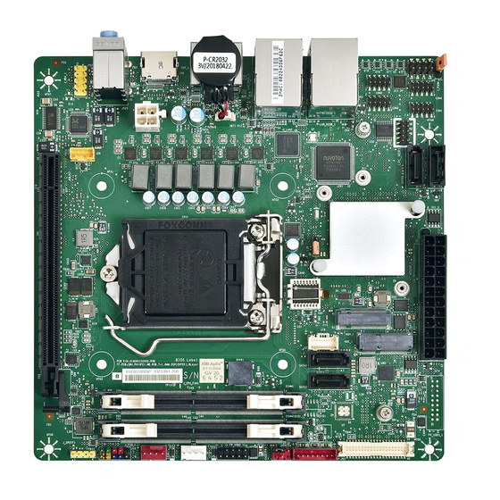
- Page 4 Desktop Board Components Figure 1 shows the approximate location of the major components on the top side of MITAC Desktop Board PH13FEI.
- Page 5 COM Port Header (RS232) COM Port Header (RS232/422/485) AT/ATX mode Header Buzzer MiAPI Header M.2 E key 2230 M.2 M key 2260/2280 COM Port Header (RS232) COM Port Header (RS232) 2. M TAC D PH13FEI C ABLE ESKTOP OARD OMPONENTS HOWN IN IGURE...
- Page 6 Processor The board supports 8 generation Intel Core processors. Other processors may be supported in the future. This board supports processors with a maximum wattage of 95 W Thermal Design Power (TDP). N O TE This board has specific requirements for providing power to the processor. Additional power required will depend on configurations chosen by the integrator.
- Page 7 C o n n e c ti n g t o t h e I n te rn a l H e a d e rs a n d C o n n e c to rs Front Panel Connector Figure 1 : Signal Name Description...
- Page 8 Figure 2: LVDS Connector Joint Tech / maker P/N : A1252WV-SF-2X20PD01 (alternative Xianyi / maker P/N : W2631-40P-R3211) LVDS(40pin) Net Name Net Name VCC3 LVDS1_LINK1_CON_DP Panel Power LVDS1_LINK0_CON_DP VCC3 LVDS1_LINK1_CON_DN Panel Power LVDS1_LINK0_CON_DN LVDS_DDC_SCL LVDS_DDC_SDA GND (CABLE_ID1) LVDS1_LINK3_CON_DP LVDS1_LINK2_CON_DP LVDS0_LINK1_CON_DP LVDS1_LINK3_CON_DN LVDS0_LINK0_CON_DP LVDS1_LINK2_CON_DN...
- Page 9 Figure 3: eDP Connector Joint Tech / maker P/N : A1252WV-SF-2X20PD01 (Alternative Xianyi / maker P/N : W2631-40P-R3211) eDP(40pin) Net Name Net Name VCC3 PCH_BL_EN Panel Power PCH_BACKLIGHT_PWM VCC3 Panel Power EDP_CPU_AUXN EDP_CPU_AUXP GND (CABLE_ID1) eDP1_DP eDP0_DP eDP1_DN eDP0_DN eDP3_DP eDP2_DP eDP3_DN eDP2_DN...
- Page 10 Figure 4: LVDS inverter power header pin-out Grand tech / maker P/N: RWA-411087-R00 (Alternative Aqua tech /maker P/N: L-WA108083R74) Signal Name Description LVDS_BKTEN_R Backlight enable LVDS_PWM Backlight PWM control 12V/19V Inverter power 12V/19V Inverter power Ground Ground BRIGHT_UP- BRIGHTNESS UP BRIGHT_DOWN- BRIGHTNESS DOWN Table 4: 8-pin LVDS inverter power header signals...
- Page 11 Table 5 Dual USB 2.0 Header Figure 6: FP Audio pin-out (pitch 2.54mm) Signal Name Description Front panel microphone input signal AUD_GND Ground used by analog audio circuits Microphone power / additional MIC MIC_BIAS input for stereo microphone support Active low signal that signals bios that an audio dongle is connected to the Presence analog header...
- Page 12 Aquatech / maker P/N : L-WA104044Y74 (alternative Grand-tek Tech / maker P/N : HWA-411047-Y00) Signal Name Front_L- Front_L+ Front_R+ Front_R- Internal header Table 7: signals Figure 8: Serial port header pin-out (pitch 2.0mm) Signal Name RXD# TXD# Table 8 Serial port header pin-out...
-
Page 13: Cmos Clear
Figure 9 Processor fan header pin-out Signal Ground +12V CPU_FAN_TACH CPU_FAN_CTRL Table 9 fan header signals Figure 10: CMOS Clear Header CMOS Clear Clear CMOS Normal Table 10: CMOS Clear behavior... - Page 14 Figure 11: M.2 M key slot For Storage pin-out For Storage signals Table 11: M.2 M key slot...
- Page 15 Figure 12: M.2 E key slot For wireless pin-out Table 12: M.2 E key slot For wireless signals...
- Page 16 Figure 13: RS422/RS485 termination mode connector Header pin-out (pitch 2.0mm) Pin Net name Pin Net name RXC-PU VCC DCDC- PD TXC-PU VCC DTRC-PD Table 13: RS422/RS485 termination mode Header signals Figure 14: SATA Header pin-out Signal Name Description Ground SATAHDR_TXP0_C SATA DATA Transmit(positive) SATAHDR_TXN0_C SATA DATA Transmit(negative)
- Page 17 Table 14: SATA Header signals Figure 15: Panel power Header pin-out Signal Name Description No pin 3.3V 3.3V option (default) 12V option LCD_VCC Send voltage to connector No pin 5V option Table 15: Panel power Header signal...
- Page 18 Figure 16: MiAPI Header Pin Net name Pin Net name MAPI_GPIO1 MAPI_GPIO2 MAPI_GPIO6 MAPI_GPIO3 MAPI_GPIO7 MAPI_GPIO4 MAPI_GPIO8 MAPI_GPIO5 10 MAPI_GPIO9 WD_Time 12 MAPI_GPIO10 Power Button 14 SMBUS_DATA UART_TX 16 SMBUS_CLK UART_RX 18 5VSB 20 NA Table 16: MiAPI Header signal Figure 17: SPDIF Header Pin Net name SPDIF-OUT...
- Page 19 Figure 18: RS422/RS485 termination mode Header (pitch 2.54mm) Pin Net name Pin Net name RXC-PU VCC DCDC- PD TXC-PU VCC DTRC-PD Table 18: RS422/RS485 termination mode Header signal Figure 19: AT/ATX mode Header AT Mode ATX Mode Table 19: AT/ATX mode Header...
-
Page 20: Bios Specification
MITAC Desktop Board PH13FEI BIOS Specification... - Page 21 MAIN PAGE Main Advanced Chipset Security Boot Save & Exit Item help BIOS Information BIOS Vender American Megatrends Core Version 5.13 Compliancy UEFI 2.7 ; PI 1.6 BIOS Version D8010A01 Build Date 06/19/2018 ME FW Version 12.0.2.1087 Processor Information Intel(R) CORE(TM) i5-8500 CPU @ 3.00GHz Memory Information Total Memory 4096 MB...
- Page 22 Field Name BIOS Version Default Value Display the version of the BIOS Comment This field is not selectable. There is no help text associated with it. Field Name Build Date Default Value Display build date of the BIOS Comment This field is not selectable. There is no help text associated with it. Field Name ME FW Version Value...
-
Page 23: Advanced Page
ADVANCED PAGE Main Advanced Chipset Security Boot Save & Exit ►CPU Configuration Item help ►Trusted Computing ►ACPI Settings ►SMART Settings ►Super IO Configuration ►Hardware Monitor →←: Select Screen ►S5 RTC Wake Settings ↑↓: Select Item ►NVMe Configuration (Available in SKU D with NVMe device) Enter: Select ►Network Stack Configuration +/- : Change Opt... - Page 24 Field Name S5 RTC Wake Settings Help Enable system to wake from S5 using RTC alarm. Comment Press Enter when selected to go into the associated Sub-Menu. Field Name NVMe Configuration Help NVMe Device Options Settings. Comment Press Enter when selected to go into the associated Sub-Menu. Field Name Network Stack Configuration Help...
-
Page 25: Cpu Configuration
CPU CONFIGURATION Main Advanced Chipset Security Boot Save & Exit Item help CPU Configuration Type Intel(R) Core(TM) 8500 CPU@ 3.00 GHz 0x906EA Speed 3000 MHz L1 Data Cache 32 KB x 6 L1 Instruction Cache 32 KB x 6 L2 Cache 256 KB x 6 L3 Cache 9 MB... - Page 26 Field Name L1 Data Cache Default Value L1 Data Cache Size Comment This field is not selectable. There is no help text associated with it. Field Name L1 Instruction Cache Default Value L1 Code Cache Size Comment This field is not selectable. There is no help text associated with it. Field Name L2 Cache Default Value...
-
Page 27: Trusted Computing
TRUSTED COMPUTING Main Advanced Chipset Security Boot Save & Exit Item help TPM20 Device Found Firmware Version: Vender : Security Device Support [Enable] →←: Select Screen Pending operation [None] ↑↓: Select Item TPM2.0 UEFI Spec Version [TCG_2] Enter: Select +/- : Change Opt F1: General Help F2: Previous Values F3: Optimized Defaults... -
Page 28: Acpi Settings
ACPI SETTINGS Main Advanced Chipset Security Boot Save & Exit Item help ACPI Settings →←: Select Screen Enable ACPI Auto Configuration [Disabled] ↑↓: Select Item Enable Hibernation [Enabled] Enter: Select ACPI Sleep State [S3 (Suspend to RAM)] +/- : Change Opt F1: General Help F2: Previous Values F3: Optimized Defaults... -
Page 29: Smart Settings
SMART SETTINGS Main Advanced Chipset Security Boot Save & Exit Item help SMART Settings →←: Select Screen SMART Self Test [Disabled] ↑↓: Select Item Enter: Select +/- : Change Opt F1: General Help F2: Previous Values F3: Optimized Defaults F4: Save & Reset ESC: Exit Version 2.18.1264. - Page 30 Field Name Serial Port 1 Configuration Help Set Parameters of Serial Port 1 (COMA) Comment Press Enter when selected to go into the associated Sub-Menu. Field Name Serial Port 2 Configuration Help Set Parameters of Serial Port 2 (COMB) Comment Press Enter when selected to go into the associated Sub-Menu.
- Page 31 2.5.1 Serial Port 1 Configuration Main Advanced Chipset Security Boot Save & Exit Serial Port 1 Configuration Item help →←: Select Screen Serial Port [Enabled] ↑↓: Select Item Device Settings IO=3F8h; IRQ=4; Enter: Select +/- : Change Opt Change Settings [Auto] F1: General Help F2: Previous Values...
- Page 32 2.5.2 Serial Port 2 Configuration Main Advanced Chipset Security Boot Save & Exit Serial Port 2 Configuration Item help →←: Select Screen Serial Port [Enabled] ↑↓: Select Item Device Settings IO=2F8h; IRQ=3; Enter: Select +/- : Change Opt Change Settings [Auto] F1: General Help F2: Previous Values...
- Page 33 2.5.3 Serial Port 3 Configuration Main Advanced Chipset Security Boot Save & Exit Serial Port 3 Configuration Item help →←: Select Screen Serial Port [Enabled] ↑↓: Select Item Device Settings IO=3E8h; IRQ=7; Enter: Select +/- : Change Opt Change Settings [Auto] F1: General Help F2: Previous Values...
- Page 34 2.5.4 Serial Port 4 Configuration Main Advanced Chipset Security Boot Save & Exit Serial Port 4 Configuration Item help →←: Select Screen Serial Port [Enabled] ↑↓: Select Item Device Settings IO=2E0h; IRQ=7; Enter: Select +/- : Change Opt Change Settings [Auto] F1: General Help Mode Configuration...
- Page 35 1T/1R RS422 with termination resistor 1T/1R RS485 with termination resistor TX ENABLE Low Active Disabled Help Configure serial port as RS232/RS422/ RS485.
-
Page 36: Hardware Monitor
HARDWARE MONITOR Main Advanced Chipset Security Boot Save & Exit PC Health Status Item help Hardware Monitor Alert Enable [Disabled] System Fan Enable [Disabled] : xx °C →←: Select Screen CPU temperature : xx °C ↑↓: Select Item CPU VR temperature : xx °C DIMM VR temperature Enter: Select... - Page 37 DIMM VR Temperature -20~120°C Fan Type Range CPU Fan Speed There are many kinds of the fans could be installed into the system. So we could only set 0 RPM for the failed fan speed, and there is also no high System Fan Speed RPM limitation.
-
Page 38: S5 Rtc Wake Settings
S5 RTC WAKE SETTINGS Main Advanced Chipset Security Boot Save & Exit Item help Wake system from S5 [Disabled] Wake up hour Wake up minute Wake up second →←: Select Screen ↑↓: Select Item Enter: Select +/- : Change Opt F1: General Help F2: Previous Values F3: Optimized Defaults... - Page 39 Field Name Wake up second(Show when Wake system from S5 set to Fixed Time) Default Value Possible Value 0 - 59 Select 0 – 59 for Second. Help...
-
Page 40: Network Stack Configuration
NETWORK STACK CONFIGURATION Main Advanced Chipset Security Boot Save & Exit Item help Network Stack [Disabled] →←: Select Screen Ipv4 PXE Support [Enabled] ↑↓: Select Item Ipv6 PXE Support [Enabled] Enter: Select +/- : Change Opt F1: General Help F2: Previous Values F3: Optimized Defaults F4: Save &... -
Page 41: Nvme Configuration
NVME CONFIGURATION Main Advanced Chipset Security Boot Save & Exit Item help NVMe Configuration ►(Device) →←: Select Screen ↑↓: Select Item Enter: Select +/- : Change Opt F1: General Help F2: Previous Values F3: Optimized Defaults F4: Save & Reset ESC: Exit Version 2.18.1264. - Page 42 2.10 INTEL(R) RAPID STORAGE CONFIGURATION Main Advanced Chipset Security Boot Save & Exit Item help Intel(R) RST 16.5.0.53439 RAID Driver ►Create RAID Volume →←: Select Screen ↑↓: Select Item RAID Volumes: Enter: Select ►Raid Volume +/- : Change Opt F1: General Help Non-RAID Physical Disks: F2: Previous Values ►HDD...
-
Page 43: Chipset Page
CHIPSET PAGE Main Advanced Chipset Security Boot Save & Exit ►System Agent (SA) Configuration Item help ►PCH-IO Configuration →←: Select Screen ↑↓: Select Item Enter: Select +/- : Change Opt F1: General Help F2: Previous Values F3: Optimized Defaults F4: Save & Reset ESC: Exit Version 2.18.1264. -
Page 44: System Agent (Sa) Configuration
SYSTEM AGENT (SA) CONFIGURATION Main Advanced Chipset Security Boot Save & Exit Item help System Agent (SA) Configuration ►Graphics Configuration →←: Select Screen ↑↓: Select Item Enter: Select +/- : Change Opt F1: General Help F2: Previous Values F3: Optimized Defaults F4: Save &... - Page 45 3.1.1 Graphics Configuration Main Advanced Chipset Security Boot Save & Exit Item help Graphics Configuration DVMT Pre-Allocated [64M] →←: Select Screen DVMT Total Gfx Mem [256M] ↑↓: Select Item Enter: Select +/- : Change Opt F1: General Help F2: Previous Values F3: Optimized Defaults F4: Save &...
-
Page 46: Pch-Io Configuration
PCH-IO CONFIGURATION Main Advanced Chipset Security Boot Save & Exit Item help PCH-IO Configuration ►SATA And RST Configuration ►HD Audio Configuration →←: Select Screen ↑↓: Select Item DeepSx Power Policies [Enabled in S4-S5] Enter: Select Wake On LAN [Enabled] +/- : Change Opt State After G3 [S5 State] F1: General Help... - Page 47 Help Specify what state to go to when power is re-applied after a power failure (G3 state). 3.2.1 SATA And RST Configuration Main Advanced Chipset Boot Security Save & Exit Item help SATA And RST Configuration SATA Mode Selection [AHCI] →←: Select Screen PCIe Storage Dev On Port 9 [Not RST Controlled]...
- Page 48 3.2.2 HD Audio Configuration Main Advanced Chipset Boot Security Save & Exit Item help HD Audio Subsystem Configuration Settings HD Audio [Enable] →←: Select Screen ↑↓: Select Item Enter: Select +/- : Change Opt F1: General Help F2: Previous Values F3: Optimized Defaults F4: Save &...
-
Page 49: Security Page
SECURITY PAGE Main Advanced Chipset Security Boot Save & Exit Item help Password Description If Only the Administrator's password is set, then this only limits access to Setup and is only asked for when entering Setup. If ONLY the User’s password is set, then this is a power on password and must be entered to boot or enter Setup. - Page 50 Field Name Secure Boot Help Secure Boot Configuration Comment Press Enter when selected to go into the associated Sub-Menu. Field Name BIOS Update Help BIOS Update support Comment Press Enter when selected to go into the associated Sub-Menu.
-
Page 51: Hdd Security
HDD SECURITY Main Advanced Chipset Security Boot Save & Exit Item help HDD Password Description : Allows Access to Set, Modify and Clear Hard Disk User Password Master Password. User Password is mandatory to Enable HDD Security. If Master password is installed (optional), it can also be used to unlock the HDD. -
Page 52: Secure Boot
SECURE BOOT Main Advanced Chipset Security Boot Save & Exit Item help System Mode Setup →←: Select Screen Secure Boot [Disabled] ↑↓: Select Item Not Active Enter: Select Secure Boot Mode [Custom] +/- : Change Opt ► Restore Factory Keys F1: General Help ►... - Page 53 4.2.1 Key Management Main Advanced Chipset Security Boot Save & Exit Item help Vender keys Not Modified Factory Key Provision [Disabled] ► Restore Factory Keys ► Reset To Setup Mode ► Export Secure Boot variables ► Enroll Efi Image ► Device Guard ready ►...
- Page 54 Help Copy NVRAM content of Secure Boot variables to files in a root folder on a file system device Field Name Enroll Efi Image Help Allow the image to run in Secure Boot mode. Enroll SHA256 Hash certificate of a PE image into Authorized Signature Database (db) Remove ‘UEFI CA’...
- Page 55 b)EFI_CERT_ X509 (DER) c)EFI_CERT_RSA2048 (bin) d)EFI_CERT_ SHAXXX 2.Authenticated UEFI Variable 3.EFI PE/COFF Image(SHA256) Key Source: Factory,External,Mixed comment Press Enter when selected to go into the associated Sub-Menu. Field Name Forbidden Signature Default Value Size:0, Keys:0, Key Source: No Keys Help Enroll Factory Defaults or load certificates from a file: 1.Public Key Certificate: a)EFI_SIGNATURE_ LIST...
-
Page 56: Bios Update
BIOS UPDATE Main Advanced Chipset Security Boot Save & Exit ►Path for ROM Image Item help Notice : →←: Select Screen ROM Image must in the root folder of storage device. ↑↓: Select Item File name must match with current BIOS project. Enter: Select +/- : Change Opt F1: General Help... -
Page 57: Fixed Boot Order Priorities
BOOT PAGE Main Advanced Chipset Security Boot Save & Exit Item help Boot Configuration Setup Prompt Timeout Bootup NumLock State [On] →←: Select Screen FIXED BOOT ORDER Priorities ↑↓: Select Item Boot Option #1 [USB Floppy] Boot Option #2 [CD/DVD] Enter: Select Boot Option #3 [USB CD/DVD]... - Page 58 Possible Value Hard Disk, USB Hard Disk, CD/DVD, USB CD/DVD, USB Key, USB Floppy , Network, Disabled Help Sets the system boot order Field Name Boot Option #2 Default Value [CD/DVD] Possible Value Hard Disk, USB Hard Disk, CD/DVD, USB CD/DVD, USB Key, USB Floppy , Network, Disabled Help Sets the system boot order...
- Page 59 Comment Press Enter when selected to go into the associated Sub-Menu. Field Name UEFI USB CDROM/DVD ROM Drive BBS Priorities Help Specifies the Boot Device Priority sequence from available USB CDROM/DVD Drives. Comment Press Enter when selected to go into the associated Sub-Menu. Field Name UEFI USB Hard Disk Drive BBS Priorities Help...
- Page 60 (LIST BOOT DEVICE TYPE) DRIVE BBS PRIORITIES Main Advanced Chipset Security Boot Save & Exit Item help Boot Option #1 [Boot Device Name 1] Boot Option #2 [Boot Device Name 2] →←: Select Screen ↑↓: Select Item Enter: Select +/- : Change Opt F1: General Help F2: Previous Values F3: Optimized Defaults...
-
Page 61: Save & Exit Page
SAVE & EXIT PAGE Main Advanced Chipset Security Boot Save & Exit Item help Save Options Discard Changes and Exit Save Changes and Reset Discard Changes and Reset Restore Defaults →←: Select Screen ↑↓: Select Item Enter: Select +/- : Change Opt F1: General Help F2: Previous Values F3: Optimized Defaults... - Page 62 RECOVERY PAGE (ACTIVE FOR 4.3 SECURE FLASH UPDATE ONLY) Main Advanced Chipset Security Boot Save & Exit Recovery Item help Please select block you want to update Reset NVRAM [Disabled] ►Process with flash update →←: Select Screen ↑↓: Select Item Enter: Select +/- : Change Opt F1: General Help...
Need help?
Do you have a question about the PH13FEI and is the answer not in the manual?
Questions and answers