Table of Contents
Advertisement
Quick Links
Advertisement
Table of Contents

Related Manuals for MiTAC PH10FEU


Summary of Contents for MiTAC PH10FEU
- Page 1 MITAC Desktop Board PH10FEU...
-
Page 2: Desktop Board Features
Desktop Board Features This chapter briefly describes the features of Desktop Board PH10FEU. Feature Summary Form Factor Micro-ATX (244 millimeters [9.6 inches] x 244 millimeters [9.6 inches]) Processor 8th generation Intel® Core processor family with up to 95 W TDP in an LGA1151... - Page 3 Display Port DVI-D RJ-45 6-stack Audio Jack (with S/PDIF) Internal I/O USB 2.0 port USB 3.0 port Desktop front panel header Audio Header (Front Panel Mic-in/Hp-out) Universal ATX Power Connector: 2x12 12V CPU ATX Power Connector: 4x2 Serial Port port (RS232) CPU FAN header (4-pin) SYS FAN header (4-pin) SATA Connector...
- Page 4 Environment Operating Temperature: 0 °C to +55 °C Storage Temperature: -40°C to +70°C Safety...
-
Page 5: Desktop Board Components
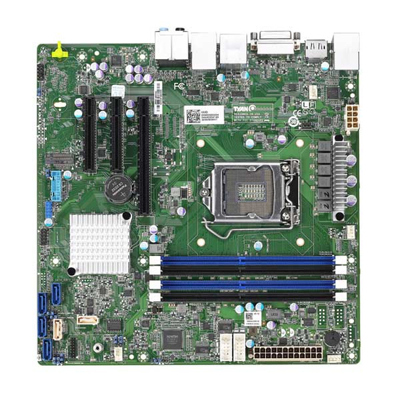
Desktop Board Components Figure shows the approximate location of the major components on the top side of MiTAC Desktop Board PH10FEU. Figure 1. MiTAC Desktop Board PH10FEU Components (Top) RJ45+USB3.0 RJ45+USB2.0 Audio DP+USB3.0 DVI-D... - Page 6 Table . MiTAC Desktop Board PH10FEU Components (Shown in the Figure) Back Panel Connectors Sys Fan header ATX Power Connector 8P LGA 1151 CPU Socket CPU FAN header DDR4 DIMM Sys Fan header ATX Power Connector 24P COM Port Sys Fan header...
-
Page 7: System Memory
Processor The board supports 8th generation Intel Core processors. Other processors may be supported in the future. This board supports processors with a maximum wattage of 95 W Thermal Design Power (TDP). NOTE This board has specific requirements for providing power to the processor. Additional power required will depend on configurations chosen by the integrator. - Page 8 MITAC Desktop Board PH10SU Hardware Specifiction...
-
Page 9: Header Definition
Header Definition CPU FAN/ SYS FAN: 4-pin CPU Fan Connector(location B, E, G, J) Signal VCC12 FAN_TACH Use this header to connect the cooling fan to your motherboard to keep the system stable and reliable. Note: A 4-pin fan is required for fan support 4pin Control Front Panel Header(location O) Signal Signal... - Page 10 Connects to the Serial ATA ready drives via the Serial ATA cable. SATA DOM Connectors (Location K, M) Name TYPE Connects to the Serial ATA ready drives via the Serial ATA cable. Internal Serial Port Header Pin-out (Location I) Signal Signal SPA_DCD SPA_DSR...
- Page 11 LAD3 CLK_33M DBG_SERIRQ DBG_PRES_N VCC3_AUX P3V3(NI) / GND RST_ESPI_RESET_N USB3.0 Header ( location Q) Signal Signal P0_RX_N P0_RX_P P0_TX_N P0_TX_P P0_N P0_P OC_N P1_P P1_N P1_TX_P P1_TX_N P1_RX_P P1_RX_N USB2.0 Header ( Location P) Signal Signal USB DATA1- USB DATA2- USBDATA1+ USB DATA2+...
- Page 12 Front Audio Header (Location S) Signal Signal MIC2-L MIC2-R FP_Present LINE2-R MIC2-JD LINE2_L LINE2-JD J38: SATA-DOM power rail option for Pin1 Signal SATA-DOM P1 Pin 1-2 Closed: P5V(Default) Pin 2-3 Closed: GND J43: SATA-DOM power rail option for Pin7 Signal SATA-DOM P7 Pin 1-2 Closed: P5V(Default) Pin 2-3 Closed: GND...
- Page 13 J60: Clear CMOS Jumper Signal VBAT RTCRST# You can reset the CMOS settings by using this jumper. This can be useful if you have forgotten your system/setup password, or need to clear the system BIOS setting. Normal (Default) 1. Power off system and disconnect power connectors from the motherboard.
- Page 14 Processor Installation (Single Socket LGA1151 for Intel Coffee lake CPU) Follow the steps below to install the processors and heat sinks. Please note that the illustrations are based on LGA1151 socket which may not look exactly like the motherboard you purchased. Therefore, the illustrations should be held for your reference only. NOTE: Please save and replace the flip CPU protection cap when returning for service.
- Page 15 Install the processor and make sure the golden arrow is in the right direction. Close the CPU socket cover. Close the socket lever.
-
Page 16: Heat Sink Installation
Heat sink Installation After installing the processor, you will need to proceed to install the heat sink. The CPU heat sink will ensure that the processor do not overheat and continue to operate at maximum performance for as long as you own them. An overheated processor is dangerous to the motherboard. The processors will overheat within seconds, enter thermal protection, and shut down if heatsinks are not installed. - Page 17 Secure the heatsink screws. Connect the heatsink fan cable.
-
Page 18: Installing The Memory
Installing the Memory Before installing memory, ensure that the memory you have is compatible with the motherboard and processor. Support (4)U-DDR4 288-pin DIMM slots Support UDIMM DDR4 (Non-ECC). Support (2) memory channels per CPU Support UDIMM 2666MHz up to 64 GB... - Page 19 Recommended Memory Population Table (Single CPU) Quantity of Single CPU Installed memory installed (CPU0 only) P0_MC0_DIM_CH_A0 √ √ P0_MC0_DIM_CH_A1 √ √ √ √ P0_MC0_DIM_CH_B0 √ P0_MC0_DIM_CH_B1 √ √ √ NOTE: 1. √ indicates a populated DIMM slot. 2. Use paired memory installation for max performance. 3.
- Page 20 Connecting External Devices Connecting external devices to the motherboard is an easy task. The motherboard supports a number of different interfaces through connecting peripherals. See the following diagrams for the details. Audio Jack Definition...
-
Page 21: Onboard Lan Led Color Definition
Onboard LAN LED Color Definition Two (2) onboard Ethernet ports have green Yellow LEDs to indicate LAN status. The chart below illustrates the different LED states. I210 1Gbps/ I219 AMT Ethernet port Link/Activity LED Scheme Left LED(LED2) Right LED(LED1) (Link/Activity) (Speed) No Link Link... -
Page 22: Installing The Power Supply
Installing the Power Supply There are Two (2) power connectors on your PH10FEU motherboard. The PH10FEU supports EPS 12V power supply. PWR1: ATX 24-Pin Power Connector Pin-out Signal Signal +3.3V +3.3V +3.3V -12V PS-ON# PWR_OK 5VSB +12V +12V +3.3V PWR2: 8-pin CPU and Memory Power Connector Pin-out... -
Page 23: Bios Setup
BIOS Setup About the BIOS The BIOS is the basic input/output system, the firmware on the motherboard that enables your hardware to interface with your software. The BIOS determines what a computer can do without accessing programs from a disk. The BIOS contains all the code required to control the keyboard, display screen, disk drives, serial communications, and a number of miscellaneous functions. - Page 24 To start the BIOS setup utility: Turn on or reboot your system. Press <F2> or <Del> during POST (<Tab> on remote console) to start the BIOS setup utility. Setup Basics The table below shows how to navigate in the setup program using the keyboard. Function ↑↓...
- Page 25 Chipset section unless you are absolutely sure of what you are doing. The Chipset defaults have been carefully chosen either by MiTAC or your system manufacturer for best performance and reliability. Even a seemingly small change to the Chipset setup options may cause the system to become unstable or unusable.
-
Page 26: Platform Information
Main Menu In this section, you can alter general features such as the date and time. Note that the options listed below are for options that can directly be changed within the Main Setup screen. BIOS Information It displays BIOS related information. Product Name It displays the product Name Platform Information... -
Page 27: Cpu Configuration
MM (Months): DD (Days): YYYY (Years) System Time Adjust the system clock. HH (24 hours format): MM (Minutes): SS (Seconds) Advanced Menu This section facilitates configuring advanced BIOS options for your system. CPU Configuration CPU Configuration parameters SATA Configuration SATA Device Option Settings... -
Page 28: Pch-Fw Configuration
PCH-FW Configuration Configure Management Engine Technology Parameters Intel® Virtual RAID on CPU This formset allows the user to manage Intel® Virtual RAID on CPU Trusted Computing Trusted Computing settings. ACPI Settings System ACPI Parameters. Watchdog Timer Configuration Watchdog Configuration Super IO Configuration System Super IO Chip Parameters Hardware Health Configuration Hardware Health Configuration... -
Page 29: Nvme Configuration
Serial Port Console Redirection Serial Port Console Redirection PCI Subsystem Settings PCI, PCI-X and PCI Express Settings USB Configuration USB Configuration Parameters. Network Stack Configuration Network Stack Settings CSM Configuration CSM Configuration, Enable/Disable Option ROM execution setting, etc NVMe Configuration NVMe Device Option Settings Onboard Device Configuration Onboard Device and Function Configuration. - Page 30 CPU Configuration Software Guard Extensions (SGX) Enable/ Disable Software Guard Extensions (SGX) Disabled / Enabled/ Software controlled...
- Page 31 Intel (VMX) Virtualization Technology When enabled, a VMM can utilize the additional hardware capabilities provided by Vanderpool Technology. Disabled / Enabled Active Processor Cores Number of cores to enable in each processor package. All / 1 / 2 / 3 / 4 / 5 Hyper- threading Enabled for Windows XP and Linux(OS optimized for Hyper-Threading Technology) and Disabled for other OS (OS not optimized for Hyper-Threading Technology).
- Page 32 Disabled / Enabled Turbo Mode Enable/Disable processor Turbo Mode (requires Intel Speed Step or Intel Speed shift to be available and enabled). Disabled / Enabled C states Enable/Disable CPU Power Management. Allows CPU to go to C states when it’s not 100% utilized. When enabled, CPU will switch to minimum speed.
- Page 33 SATA Configuration SATA Mode Selection Determines how SATA controller(s) operate. AHCI / RAID Serial ATA Port 0/1/2/3/4/5 Hot Plug Designates this port as Hot Pluggable. Disabled / Enabled SATA Device Type Identify the SATA port is connected to Solid State Drive or Hard Dish Drive. Hard Disk Drive / Solid State Drive...
- Page 34 PCH-FW Configuration ME State When Disabled ME will be not into ME Temporarily Disabled Mode. Disabled / Enabled AMT BIOS Features When disabled AMT BIOS Features are no longer supported and user is no longer able to access MEBx Setup. Note: This option does not disable Manageability Features in FW.
- Page 35 Firmware Update Configuration Me FW Image Re-Flash Enable/Disable Me FW Image Re- Flash function. Disabled / Enabled...
- Page 36 Trusted Computing Security Device Support Enable or disable BIOS support for security device. O.S. will not show Security Device. TCG EFI protocol and INT1A interface will not be available. Disable / Enable...
- Page 37 ACPI Settings ACPI Sleep State Select the highest ACPI sleep state the system will enter when the SUSPEND button is pressed. Suspend Disabled / S3 (Suspend to RAM) S3 Video Repost Enables or disables S3 Video Repost. Disabled / Enabled...
- Page 38 Watchdog Timer Configuration Watchdog Mode The duration of enabling Watchdog Timer. When Watchdog time-out occurs, System will roboot immediately. Disabled / POST / OS / Power ON...
- Page 39 Super IO Configuration Serial Port 1 Configuration Set Parameters of Serial Port 1 (COMA) Serial Port 2 Configuration Set Parameters of Serial Port 2 (COMB)
- Page 40 Serial Port 1 Configuration Serial Port Enable or Disable Serial Port (COM) Disabled / Enabled Device Settings Read only. Change Settings Select an optimal setting for Super IO Device. Auto / IO=3F8h; IRQ=4; / IO=3F8h, IRQ=3, 4, 5, 6, 7, 9, 10, 11, 12; / IO=2F8h;...
- Page 41 / IO=2E8h, IRQ=3, 4, 5, 6, 7, 9, 10, 11, 12; Serial Port 2 Configuration Serial Port Enable or Disable Serial Port (COM) Disabled / Enabled Device Settings Read only. Change Settings Select an optimal setting for Super IO Device. Auto / IO=2F8h;...
- Page 42 / IO=2F8h; IRQ=3, 4, 5, 6, 7, 9, 10, 11, 12; / IO=3E8h, IRQ=3, 4, 5, 6, 7, 9, 10, 11, 12; / IO=2E8h, IRQ=3, 4, 5, 6, 7, 9, 10, 11, 12; Hardware Health Configuration Auto Fan Control Auto Fan Control help. Disabled / Enabled NOTE: Auto Fan Control must be set to [Enabled] PWM Minimal Duty Cycle menu will...
- Page 43 15% Duty Cycle / 30% Duty Cycle / 45% Duty Cycle Sensor Data Register Monitoring S5 RTC Wake Settings...
- Page 44 Wake system from S5 Enable or disable system wake on alarm event. Select Fixed time, system will wake on the hr::min::sec specified. Select dynamic time, system will wake on the current time+ increase minute(s) Disabled / Fixed time / Dynamic time Serial Port Console Redirection COM1/COM2/COM3(Pci Bus0,Dev22,Func3) Console Redirection...
- Page 45 Legacy Console Redirection Legacy Console Redirection Settings Serial Port for Out-Of-Band Management/Windows Emergency Services (EMS) Console Redirection Console redirection enable or disable. Disabled / Enabled Console Redirection Settings The settings specify how the host computer (which the user is using) will exchange data. Both computers should have the same or compatible settings.
- Page 46 Emulation: ANSI: Extended ASCII char set. VT100: ASCII char set. VT100+: Extends VT100 to support color function keys, etc. VT-UTF8: Uses UTF8 encoding to map Unicode chars onto 1 or more bytes. VT100 / VT100+ / VT-UTF8 / ANSI Bits per Second Select serial port transmission speed.
- Page 47 are full, a ‘stop’ signal can be sent to stop the data flow. Once the buffers are empty, a ‘start’ signal can be sent to re-start the flow. Hardware flow control uses two wires to send start/stop signal. None / Hardware RTS/CTS VT-UTF8 Combo Key Support Enable VT-UTF8 Combination Key Support for ANSI/VT100 terminals.
- Page 48 Legacy Console Redirection Settings Legacy Serial Redirected Port Select a COM port to display redirection of Legacy OS and Legacy OPROM Messages COM1 / COM2 / COM3(Pci Bus0,Dev22,Func3) Resolution On Legacy OS, the Number of Rows and Columns supported redirection 80x24 / 80x25 Redirect After POST When Bootloader is selected then Legacy Console Redirection is disabled before booting to legacy OS.
- Page 49 Serial Port for Out-Of-Band Management/Windows Emergency Services (EMS) Console Redirection Settings Out-of Band Mgmt Port Microsoft Windows Emergency Management Services (EMS) allows for remote management of a Windows Server OS through a serial port. COM1 / COM2 / COM3(Pci Bus0,Dev22,Func3) Terminal Type VT-UTF8 is the preferred terminal type for out-of-band management.
- Page 50 9600 / 19200 / 57600/ 115200 Flow Control Flow Control can prevent data loss from buffer overflow. When sending data, if the receiving buffers are full, a ‘stop’ signal can be sent to stop the data flow. Once the buffers are empty, a ‘start’ signal can be sent to restart the flow.
- Page 51 Enabled / Disabled SR-IOV Support If system has SR-IOV capable PCIe devices, this option Enable or Disable Single root IO virtualization Support Enabled / Disabled USB Configuration Legacy USB Support Enables USB legacy support. AUTO option disables legacy support if no USB devices are connected. DISABLE option will keep USB devices available only for EFI applications.
- Page 52 Device reset time-out USB mass storage device Start Unit command time-out. 10 sec / 20 sec / 30 sec / 40 sec Device power-up delay Maximum time the device will take before it properly reports itself to the Host Controller. AUTO uses default value: for a Root port it is 100 ms, for a Hub port the delay is taken from Hub descriptor.
- Page 53 CSM Configuration CSM support Enable/Disable CSM Support Enabled / Disabled Option ROM Messages Set display mode for Option ROM Force BIOS / Keep Current INT19 Trap Resource BIOS reaction on INT19 trapping by option ROM: IMMEDIATE - execute the trap right away; POSTPONED – execute the trap during legacy boot. Immediate / Postponed...
- Page 54 Boot option filter This option controls Legacy/UEFI ROMs priority UEFI and Legacy / Legacy only / UEFI only Network Controls the execution of UEFI and legacy PXE OpROM Do not launch / UEFI / legacy Storage Controls the execution of UEFI and legacy PXE OpROM Do not launch / UEFI / legacy Video Controls the execution of UEFI and legacy PXE OpROM...
- Page 55 NVMe Configuration No NVMe Device Found Onboard Device Configuration...
- Page 56 LAN1(I210) Enable or disable onboard LAN1(I210). Disabled / Enabled LAN1 OPROM Enable or disable onboard LAN1 OPROM. Disabled / PXE / iSCSI LAN2 (I219) Enable or disable onboard LAN2 (I219) Disabled / Enabled LAN2 OPROM Enable or disable onboard LAN2 OPROM Disabled Chassis Intrusion Detection Enabled: When a chassis open event is detected, the BIOS will record the event.
- Page 57 iSCSI Configuration iSCSI Name The worldwide unique name of iSCSI Initiator. Only IQN format is accepted. Range is from 4 to 223. Press enter to input a iSCSI Initiator Name...
- Page 58 Chipset Menu North Bridge System Agent (SA) Parameters. South Bridge PCH Parameters...
- Page 59 North Bridge Configuration VT-d VT-d capability Disabled / Enabled Memory Configuration Memory Configuration Parameters Graphics Configuration Graphics Configuration...
-
Page 60: Memory Configuration
Memory Configuration Memory Test on Warm Boot Enable Or Disable Base Memory Test Run on Warm Boot Disabled Enabled Maximum Memory Frequency Maximum Memory Frequency Selections in Mhz. Valid values should match the refclk, i.e. divide by 133 or 100 Auto / 2133 / 2400 / 2667 ECC Support Enable/ disable DDR Ecc Support... -
Page 61: Graphics Configuration
Graphics Configuration Primary Display Select which of IGFX/PEG/ PCI Graphics device should be Primary Display or select SG for Switchable Gfx. Auto / IGFX / PEG / PCI Internal Graphics Keep IGFX enabled based on the setup options. Auto / Disabled / Enabled... - Page 62 South Bridge Configuration HD Audio Configuration HD Audio Subsystem Configuration Settings DeepSx Power Configure the DeepSx Mode configuration. Disabled Enabled in S4-S5 Wake on LAN Enable/Disable integrated LAN to wake the system. Enabled / Disabled High Precision Timer Enable or Disable the High Precision Event Timer...
- Page 63 Disabled Enabled Restore AC Power Loss Select AC power state when power is re-applied after a power failure. Power Off / Power On / Last State HD Audio Configuration HD Audio Control Detection of the HD- Audio device. Disabled = HAD will be unconditionally disabled Enabled = HAD will be unconditionally enabled.
-
Page 64: Administrator Password
Enable/Disable Audio DSP. Disabled Enabled Security Administrator Password Set Administrator Password. User Password Set User Password. Security Frozen Mode Enable or disable HDD security freeze lock. Disable to support secure erase function. Disabled / Enabled... - Page 65 Secure Boot Customizable Secure Boot settings Secure Boot Configuration Submenu Secure Boot Secure Boot feature is Active if Secure Boot is Enabled, Platform Key (PK) is enrolled and the System is in User mode. The mode change requires platform reset Disabled / Enabled Secure Boot Mode Secure Boot mode selector.
- Page 66 Restore Factory Keys Submenu Restore Factory Keys Force System to User Mode. Install factory default Secure Boot Key databases. When Press ‘Yes’ to proceed When Press ‘No’ to cancel...
- Page 67 Reset To Setup Mode Submenu Reset To Setup Mode Delete all Secure Boot key databases from NVRAM Deleting all variables will reset the System to setup Mode When Press ‘Yes’ to proceed When Press ‘No’ to cancel Key Management Enables experienced users to modify Secure Boot variables...
- Page 68 Key Management Factory Keys Provision Install factory default Secure Boot Keys after the platform reset and while the System is in Setup Mode. Disabled / Enabled Restore Factory Keys Force System to User Mode. Install Factory Default Secure Boot Key databases. Reset To Setup Mode Delete all Secure Boot Key databases from NVRAM Export Secure Boot variables...
- Page 69 Enroll Efi Image Allow the image to run in Secure Boot mode. Enroll SHA256 Hash certificate of a PE image into Authorized Signature Database(db) Remove ‘UEFI CA’ from DB Device Guard ready system must not list ‘ Microsoft’ UEFI CA’ Certificate in Authorized Signature database (db) Restore DB defaults Restore DB variable to Factory defaults...
- Page 70 1. Public Key Certificate in: a) EFI_SIGNATURE_LIST b) EFI_CERT_X509 (DER encoded) c) EFI_CERT_RSA2048 (bin) d) EFI_CERT_SHA256,384,512 2. Authenticated UEFI Variable 3. EFI PE/COFF Image(SHA256) Key Source: Default, External, Mixed, Test Authorized Signatures Enroll Factory Defaults or load certificates from a file: 1.
- Page 71 Forbidden Signatures Enroll Factory Defaults or load certificates from a file: 1. Public Key Certificate in: a) EFI_SIGNATURE_LIST b) EFI_CERT_X509 (DER encoded) c) EFI_CERT_RSA2048 (bin) d) EFI_CERT_SHA256,384,512 2. Authenticated UEFI Variable 3. EFI PE/COFF Image(SHA256) Key Source: Default, External, Mixed, Test Authorized TimeStamps Enroll Factory Defaults or load certificates from a file: 1.
- Page 72 OsRecovery Signatures Enroll Factory Defaults or load certificates from a file: 1. Public Key Certificate in: a) EFI_SIGNATURE_LIST b) EFI_CERT_X509 (DER encoded) c) EFI_CERT_RSA2048 (bin) d) EFI_CERT_SHA256,384,512 2. Authenticated UEFI Variable 3. EFI PE/COFF Image(SHA256) Key Source: Default, External, Mixed, Test...
- Page 73 Boot Setup Prompt Timeout Number of seconds to wait for setup activation key. 65535 (0xFFFF) means indefinite waiting. Bootup NumLock State Select the keyboard NumLock state. Off / On Quiet Boot Enable or disable Quiet Boot option. Disabled / Enabled Boot Option #1 Sets the system boot order Device Name / Disabled...
- Page 74 Boot Option #2 Device Name / Disabled Endless boot Restart the INT19 boot process automatically if all IPL devices fail to boot. Wait for “ESC” if Error Wait for ESC stop when BIOS has error appeared. Disabled / Enabled Hard Drive BBS Priorities Set the order of the Legacy devices in this group...
- Page 75 Hard Drive BBS Priorities Configuration Boot Option #1 Sets the system boot order. Device Name / Disabled...
- Page 76 Save & Exit Save Changes and Exit Exit system setup after saving the changes. Discard Changes and Exit Exit system setup without saving any changes. Save Changes and Reset Reset the system after saving the changes. Discard Changes and Reset Reset system setup without saving any changes.
- Page 77 Save Changes Save changes done so far to any of the setup options. Discard Changes Discard changes done so far to any of the setup options. Restore Defaults Restore/Load Default values for all the setup options. Save as User Defaults Save the changes done so far as User Defaults.
Need help?
Do you have a question about the PH10FEU and is the answer not in the manual?
Questions and answers