Table of Contents
Advertisement
Quick Links
Advertisement
Table of Contents

Subscribe to Our Youtube Channel
Related Manuals for MiTAC PD10AI


Summary of Contents for MiTAC PD10AI
- Page 1 MITAC Desktop Board PD10AI Product Guide...
-
Page 2: Desktop Board Features
Desktop Board Features This chapter briefly describes the features of Desktop Board PD10AI. Below to summarizes the major features of the Desktop Board. Feature Summary TAC D PD10AI F AB LE ES KTOP OARD EATUR ES Low-profile Mini-ITX (20 millimeters [0.79 inches] x 170.18 Form Factor millimeters [6.7 inches] x 170.18 millimeters [6.7 inches]) - Page 3 LAN Support Intel I211-AT (10/100/1000 Mb/s) Ethernet LAN controller *2 BIOS resident in a Serial Peripheral Interface (SPI) Flash device BIOS Support for Advanced Configuration and Power Interface (ACPI), and System Management BIOS (SMBIOS) Nuvoton NCT6793D based subsystem, including: Hardware ...
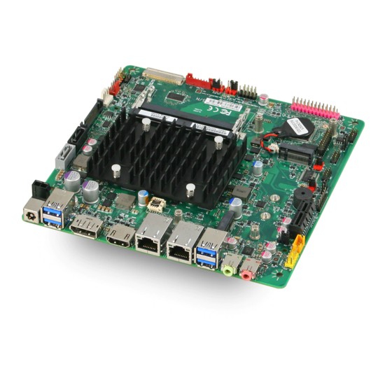
- Page 4 Desktop Board Components Figure shows the approximate location of the major components on the top side of MiTAC Desktop Board PD10AI. Figure: MiTAC Desktop Board PD10AI Components (Top)
- Page 5 TAC D PD10AI C AB LE ES KTOP OAR D OMPONENTS Back Panel Connectors 12V 2-PIN DC-in M.2 Key-E SATA 7-Pin Connector Com2 RS232 Power Select SATA Power Connector SO-DIMM slot CPU Fan Header System Fan Header Chassis Front I/O Header...
- Page 6 Processor MITAC Desktop Board PD10AI includes a passively-cooled, Intel Apollo Lake N3350/N4200 processor with integrated graphics and memory controller. The processor is soldered to the Desktop Board and is not customer upgradeable. NOTE The board is designed to be passively cooled in a properly ventilated chassis. Chassis venting locations are recommended above the processor heatsink area for maximum heat dissipation effectiveness.
- Page 7 Connecting to the Internal Headers and Connectors LVDS feature: 40-pin LVDS connector must be right-angled, single-row shrouded colored white, as shown in Figure 1 (part number reference: ACES 88341-40xx). Figure 1: Panel 40-pin LVDS connector Table 1: 40-pin LVDS connector pin-out...
- Page 8 eDP feature: 40-pin eDP connector must be right-angled, single-row shrouded colored black, as shown in Figure 2 (part number reference: ACES 50203-04001-001). Figure 2: Panel 40-pin LVDS connector Table 2: 40-pin eDP connector pin-out...
- Page 9 Figure 3: Panel LCD voltage selection header (Location Signal Name Description No pin 3.3V 3.3V option 12V option LCD_VCC Send voltage to connector No pin 5V option (default) Table 3: Panel LCD voltage selection header pin-out (Location Figure 4: Backlight inverter voltage selection header(Location...
- Page 10 Pin Signal Description 1 Key No pin 2 5V 5V option (default) 3 8v~24V Vin option same as DC-IN power rail 4 BKLT_PWR Send voltage to connector 5 Key No pin 6 12V 12V option Table 4: Backlight inverter voltage selection header pin-out(Location LVDS inverter power header pin-out (part number reference: Foxconn HF5508).
- Page 11 5 BKLT_GND/Brightness_GND Ground (shared) 6 BKLT_GND/Brightness_GND Ground (shared) 7 Brightness_Up Panel brightness increase 8 Brightness_Down Panel brightness decrease Table 5: 8-pin FPD power connector pin-out Figure 6: Front panel audio header Pin Signal name Description 1 MIC Front panel microphone input signal (biased when supporting stereo microphone) 2 AUD_GND Ground used by analog audio circuits 3 MIC_BIAS...
- Page 12 Pin Signal name Description 1 PORT 1L Analog Port 1 - Left channel (Microphone) 2 GND Ground 3 PORT 1R Analog Port 1 - Right channel (Microphone) Active low signal that signals BIOS that an Intel® HD Audio dongle is connected to the analog header.
- Page 13 3 Front_R+ Analog front right (differential positive) Analog front right (differential 4 Front_R- negative) Table 7: Internal stereo speakers header pinout Figure 8:SATA Power Cable pin-out Signal Name Description VCC3 Power VCC3 Power VCC3 Power Ground Ground Ground Power Power Power Ground Ground...
- Page 14 +12V Power +12V Power Table 8:SATA Power Cable signals Figure 9:SATA Header pin-out Signal Name Description Ground SATAHDR_TXP0_C SATA DATA Transmit(positive) SATAHDR_TXN0_C SATA DATA Transmit(negative) Ground SATAHDR_RXN0_C SATA DATA Receive(negative) SATAHDR_RXP0_C SATA DATA Receive(positive) Ground Table 9:SATA Header signals...
- Page 15 Figure 10: Front panel USB header pin-out Pin Signal Pin Signal +5V DC +5V DC Data (negative) Data (negative) Data (positive) Data (positive) Ground Ground Key (no pin) No Connect Table 10: Front panel USB header signals Figure 11: Front panel main header pin-out Pin Signal Name Description Signal Name...
- Page 16 GROUND Ground POWER_SWITCH# [In] Power switch RESET_SWITCH# [In] Reset switch GROUND Ground +5V_DC Power No pin Table 11: Front panel main header signals Figure 12: serial port pin out Signal Signal COM3_P1_40mils DCD (Data Carrier Detect) NRX3 RXD# (Receive Data) NTX3 TXD# (Transmit Data) NDTR3...
- Page 17 Figure 13: power RS232 header pin-out J26 pin out V_12P NDCD1 COM1_P9 V+5P J27 pin out V_12P NRI2 COM2_P9 V+5P Table 13: power RS232 Serial port header signals...
- Page 18 Figure 14: Parallel port header pin-out Standard Signal Name ECP Signal Name EPP Signal Name STROBE# STROBE# WRITE# AUTOFD# AUTOFD#, HOSACK DATASTB# FAULT# FAULT#, PERIPHREQST# FAULT# INT# INT#, REVERSERQST# RESET# SLCTIN# SLCTIN# ADDRSTB# GROUND GROUND GROUND GROUND GROUND GROUND GROUND GROUND GROUND GROUND...
- Page 19 Standard Signal Name ECP Signal Name EPP Signal Name GROUND GROUND GROUND BUSY BUSY#, PERIPHACK WAIT# GROUND GROUND GROUND PERROR PE, ACKREVERSE# GROUND GROUND GROUND SELECT SELECT SELECT KEY (no pin) KEY (no pin) KEY (no pin) Table 24: Parallel port header signals Figure 15: Clear CMOS CMOS Jumper Header location...
- Page 20 Figure 16: AT/ATX mode header pin-out AT/ATX Jumper Header location Default Pin2 and Pin3 Auto PWR ON Pin1 and Pin2 Table 46: AT/ATX mode header pin-out Figure 17: CPU fan header Signal Ground +12V CPU_FAN_TACH CPU_FAN_CTRL Table 57: Figure 27: CPU fan header...
- Page 21 Figure 18: system fan header Signal Ground +12V SYSFANIN Table 68: System fan header Figure 19: M.2 E key slot For wireless pin-out...
- Page 22 Table 19: M.2 E key slot For wireless signals Figure 20: M.2 B key slot for storage pin-out Signal Name Signal Name CONFIG_3 +Vcc(3.3v)
- Page 23 +Vcc(3.3v) POWER_OFF# W disable USB D0+ 10 GPIO USB D0- 12 Module Key 13 Module Key 14 Module Key 15 Module Key 16 Module Key 17 Module Key 18 Module Key 19 Module Key 20 X 22 X 23 X 24 X 25 X 26 X...
- Page 24 37 X 38 DEVSLP 39 GND 40 X 41 SATA B+ 42 X 43 SATA B- 44 X 45 GND 46 X 47 SATA A- 48 X 49 SATA A+ 50 Platform Reset 51 GND 52 Clock request 53 REFCLKN 54 PCIE_WAKE 55 REFCLKP 56 X...
- Page 25 71 GND 72 +Vcc(3.3v) 73 GND 74 +Vcc(3.3v) 75 GND Table 20: M.2 B key slot For storage signals The MiAPI port header must be 2x13, 2.54mm pitch, colored pink and keyed at pin 26, as defined in Table 24: Parallel port header signals 13.
- Page 26 MAPI_GPIO10 22 GND 23 SMB_MAIN_DATA 24 GND 25 SMB_MAIN_CLK 26 KEY (no pin) Table 21: MiAPI header signals...
- Page 27 MITAC Desktop Board PD10AI BIOS Specifiction...
- Page 28 Main Page Main Advanced Chipset Security Boot Save & Exit BIOS Information Item help BIOS Vender American Megatrends Core Version 5.12 Compliancy UEFI 2.5; PI 1.4 BIOS Version D7670X03 Build Date 11/07/2016 Processor Information Genuine Intel® CPU @ 1.50GHz →←: Select Screen SATA Devices ↑↓: Select Item SATA Port0...
- Page 29 System Date [Mon, mm/dd/yyyy] System Time [hh:mm:ss] Version 2.18.1263. Copyright (C) 2017 American Megatrends, Inc. Field Name BIOS Vender Default Value AMI Megatrends Comment This field is not selectable. There is no help text associated with it. Field Name Core Version Default Value 5.12 Comment...
- Page 30 Default Value Display build time of the BIOS Comment This field is not selectable. There is no help text associated with it. Field Name Processor Information Value Display the installed CPU brand. Comment This field is not selectable. There is no help text associated with it. Field Name SATA port 0 Value...
- Page 31 Comment This field is not selectable. There is no help text associated with it. Field Name System Language Default Value [English] Possible Value [English] Help Choose the system default language Field Name System Date Default Value [xxx, mm dd yyyy] Possible Value [xxx, xx:xx:xxxx] Help...
-
Page 32: Advanced Page
Advanced Page Main Advanced Chipset Security Boot Save & Exit LAN1 [Enable] Item help LAN2 [Enable] Wireless LAN RF [Enable] Intel(R) I211 Gigabit Network Connection -xx:xx:xx:xx:… Intel(R) I211 Gigabit Network Connection -xx:xx:xx:xx:… Driver Health ► ACPI Settings ► SMART settings ►... - Page 33 Field Name LAN1 Default Value Enabled Possible Value Disabled Enabled Help Enable/Disable LAN1 Field Name LAN2 Default Value Enabled Possible Value Disabled Enabled Help Enable/Disable LAN2 Field Name Wireless LAN RF Default Value Enabled Possible Value Disabled Enabled Help Enable/Disable Wireless Lan RF Field Name Intel(R) I211 Gigabit Network Connection -xx:xx:xx:xx:…...
- Page 34 Field Name Intel(R) I211 Gigabit Network Connection -xx:xx:xx:xx:… Help Configure Gigabit Ethernet device parameters Field Name Driver Health Help Provides Health Status for the Drivers/Controllers Field Name ACPI Settings Help System ACPI Parameters. Comment Press Enter when selected to go into the associated Sub-Menu. Field Name SMART Settings Help...
- Page 35 Field Name S5 RTC Wake Settings Help Enable system to wake from S5 using RTC alarm Comment Press Enter when selected to go into the associated Sub-Menu. Field Name CPU Configuration Help CPU Configuration Parameters. Comment Press Enter when selected to go into the associated Sub-Menu. Field Name Network Stack Configuration Help...
- Page 36 Intel(R) I211 Gigabit Network Connection-xx:xx:xx:xx:… Main Advanced Chipset Security Boot Save & Exit ► NIC Configuration Item help Blink LEDS UEFI Driver Intel(R) PRO/1000 7.0 Device Name Intel(R) I211 Gigabit….. Chip Type Intel i211 →←: Select Screen PCI Device ID 1539 ↑↓: Select Item PCI address...
- Page 37 Field Name Blink LEDS Default Value Possible Value 0~15 Help Identify the physical network port by blinking the associated LED. Field Name UEFI Driver Default Value Intel(R) PRO/1000 7.0… Comment This field is not selectable. There is no help text associated with it. Field Name Device Name Default Value...
- Page 38 Field Name Link Status Default Value [Disconnected] Comment This field is not selectable. There is no help text associated with it. Field Name MAC Address Default Value XX:XX:XX:XX:XX:XX Comment This field is not selectable. There is no help text associated with it.
- Page 39 NIC configuration 2.2.1 Main Advanced Chipset Security Boot Save & Exit Item help Link Speed [Auto Negotiated] Wake On Lan [Enable] →←: Select Screen ↑↓: Select Item Enter: Select +/- : Change Opt F1: General Help F2: Previous Values F3: Optimized Defaults F4: Save &...
- Page 40 100 Mbps Half 100 Mbps Full Help Specifies the port speed used for the selected boot protocol. Field Name Wake On LAN Default Value Enable Possible Value Enable Disable Help Enables the server to be powered on using an in-band magic packet. Intel(R) I211 Gigabit...
- Page 41 F2: Previous Values MAC Address 00:22:4D:B8:C3:48 F3: Optimized Defaults F4: Save & Reset ESC: Exit Version 2.18.1263. Copyright (C) 2017 American Megatrends, Inc. Field Name NIC Configuration Help Click to configure the network device port. Comment Press Enter when selected to go into the associated Sub-Menu. Field Name Blink LEDS Default Value...
- Page 42 Comment This field is not selectable. There is no help text associated with it. Field Name PCI Device ID Default Value 1539 Comment This field is not selectable. There is no help text associated with it. Field Name PCI Address Default Value 01:00:00 Comment...
- Page 43 NIC configuration 2.3.1 Main Advanced Chipset Security Boot Save & Exit Item help Link Speed [Auto Negotiated] Wake On Lan [Enable] →←: Select Screen ↑↓: Select Item Enter: Select +/- : Change Opt F1: General Help F2: Previous Values F3: Optimized Defaults F4: Save &...
-
Page 44: Driver Health
100 Mbps Half 100 Mbps Full Help Specifies the port speed used for the selected boot protocol. Field Name Wake On LAN Default Value Enable Possible Value Enable Disable Help Enables the server to be powered on using an in-band magic packet. Driver health Main Advanced... - Page 45 F2: Previous Values F3: Optimized Defaults F4: Save & Reset ESC: Exit Version 2.18.1263. Copyright (C) 2017 American Megatrends, Inc. Field Name Intel(R) PRO/1000 7.3.20 PCI-E Help Provides Health Status for the Drivers/Controllers Comment Press Enter when selected to go into the associated Sub-Menu. Field Name Intel(R) PRO/1000 7.3.06 PCI-E Help...
- Page 46 Intel(R) PRO/1000 7.3.06 PCI-E 2.4.1 Main Advanced Chipset Security Boot Save & Exit Controller 73999398 Child 0 Healthy Item help Intel(R) I211 Gigabit Network Connection Healthy →←: Select Screen ↑↓: Select Item Enter: Select +/- : Change Opt F1: General Help F2: Previous Values F3: Optimized Defaults F4: Save &...
- Page 47 Field Name Intel(R) I211 Gigabit Network Connection Help Provides Health Status for the Drivers/Controllers Comment This field is not selectable. There is no help text associated with it. Intel(R) PRO/1000 7.3.06 PCI-E 2.4.2 Main Advanced Chipset Security Boot Save & Exit Controller 73999398 Child 0 Healthy Item help...
-
Page 48: Acpi Settings
Field Name Controller xxxxxxxx Child 0 Help Provides Health Status for the Drivers/Controllers Comment This field is not selectable. There is no help text associated with it. Intel(R) I211 Gigabit Network Connection Field Name Help Provides Health Status for the Drivers/Controllers Comment This field is not selectable. - Page 49 F4: Save & Reset ESC: Exit Version 2.18.1263. Copyright (C) 2017 American Megatrends, Inc. Field Name Enable ACPI Auto Configuration Default Value [Disabled] Possible Value Enabled Disabled Help Enables or Disables BIOS ACPI Auto Configuration. Field Name Enable Hibernation Default Value [Enabled] Possible Value Enabled...
-
Page 50: Smart Settings
SMART Settings Main Advanced Chipset Security Boot Save & Exit SMART Settings Item help SMART Self Test [Disabled] →←: Select Screen ↑↓: Select Item Enter: Select +/- : Change Opt F1: General Help F2: Previous Values F3: Optimized Defaults F4: Save & Reset ESC: Exit Version 2.18.1263. - Page 51 NCT6104DSEC Super IO Configuration Main Advanced Chipset Security Boot Save & Exit NCT6104DSEC Super IO Configuration Item help Super IO chip NCT6104DSEC ► Serial Port 1 Configuration" ► Serial Port 2 Configuration" ► Serial Port 3 Configuration" ► Serial Port 4 Configuration" →←: Select Screen ↑↓: Select Item Enter: Select...
- Page 52 Field Name Serial Port 2 Configuration" Help Set Parameters of Serial Port 2 (COMB) Comment Press Enter when selected to go into the associated Sub-Menu. Field Name Serial Port 3 Configuration" Help Set Parameters of Serial Port 3 (COMC) Comment Press Enter when selected to go into the associated Sub-Menu.
- Page 53 F1: General Help F2: Previous Values F3: Optimized Defaults F4: Save & Reset ESC: Exit Version 2.18.1263. Copyright (C) 2017 American Megatrends, Inc. Field Name Serial Port Default Value Enabled Possible Value Disabled Enabled Help Enable or Disable Serial Port (COM) Field Name Device Settings Default Value...
- Page 54 →←: Select Screen ↑↓: Select Item Enter: Select +/- : Change Opt F1: General Help F2: Previous Values F3: Optimized Defaults F4: Save & Reset ESC: Exit Version 2.18.1263. Copyright (C) 2017 American Megatrends, Inc. Field Name Serial Port Default Value Enabled Possible Value Disabled...
- Page 55 Serial port 3 Configuration 2.7.3 Main Advanced Chipset Security Boot Save & Exit Serial Port 3 Configuration Item help Serial Port [Enabled] Device Settings IO=258h; IRQ=11; Com3 set to [3T/5R RS-232] →←: Select Screen ↑↓: Select Item Enter: Select +/- : Change Opt F1: General Help F2: Previous Values F3: Optimized Defaults...
- Page 56 Enabled Help Enable or Disable Serial Port (COM) Field Name Device Settings Default Value IO=258h; IRQ=11; Comment This field is not selectable. There is no help text associated with it. Field Name Com3 set to Default Value 3T/5R RS-232 Possible Value 1T/1R RS-422 3T/5R RS-232 1T/1R RS-485 TX ENABLE Low Active...
- Page 57 Serial port 4 Configuration 2.7.4 Main Advanced Chipset Security Boot Save & Exit Serial Port 4 Configuration Item help Serial Port [Enabled] Device Settings IO=260h; IRQ=11; Com4 set to [3T/5R RS-232] →←: Select Screen ↑↓: Select Item Enter: Select +/- : Change Opt F1: General Help F2: Previous Values F3: Optimized Defaults...
- Page 58 Help Enable or Disable Serial Port (COM) Field Name Device Settings Default Value IO=260h; IRQ=11; Comment This field is not selectable. There is no help text associated with it. Field Name Com4 set to Default Value 3T/5R RS-232 Possible Value 1T/1R RS-422 3T/5R RS-232 1T/1R RS-485 TX ENABLE Low Active...
-
Page 59: Nct6793D Super Io Configuration
NCT6793D Super IO Configuration Main Advanced Chipset Security Boot Save & Exit NCT6793D Super IO Configuration Item help Serial Port 1 [Enabled] Serial Port 2 [Enabled] Parallel Port [Enabled] →←: Select Screen Device Mode [STD Printer Mode] ↑↓: Select Item Enter: Select +/- : Change Opt F1: General Help... - Page 60 Possible Value Enabled Disabled Help Enable or Disable Serial Port (COM) Field Name Serial Port 2 Default Value [Enabled] Possible Value Enabled Disabled Help Enable or Disable Serial Port (COM) Field Name Parallel Port Default Value [Enabled] Possible Value Enabled Disabled Help Enable or Disable Parallel Port (LPT/LPTE)
- Page 61 ECP-1.7 and SPP Mode Help Change the Printer Port mode. Comment SKU-S did not have Parallel port menu...
- Page 62 S5 RTC Wake Settings(No function when DeepSx Power Policies enabled) Main Advanced Chipset Security Boot Save & Exit Wake system from S5 [Disabled] Item help Wake up hour Wake up minute Wake up second →←: Select Screen ↑↓: Select Item Enter: Select +/- : Change Opt F1: General Help...
- Page 63 Fixed Time Dynamic Time Help Enabler or disable System wake on alarm event, Select FixedTime, system will wake on the hr::min::sec specified. Select DynamicTime , system will wake on the current time + Increase minute (s) Field Name Wake up hour(Show when Wake system from S5 set to Fixed Time) Default Value Possible Value...
-
Page 64: Cpu Configuration
CPU Configuration Main Advanced Chipset Security Boot Save & Exit CPU Configuration Item help Intel(R) Core(TM) CPU [CPU NAME] @ [CPU Freq.] GHz CPU Signature 406c3 Microcode Patch Max CPU Speed 1600 MHz Min CPU Speed 480 MHz Processor Cores Intel HT Technology Not Supported Intel VT-x Technology... - Page 65 +/- : Change Opt F1: General Help F2: Previous Values F3: Optimized Defaults F4: Save & Reset ESC: Exit Version 2.18.1263. Copyright (C) 2017 American Megatrends, Inc. Field Name CPU Configuration Default Value [Intel CPU Brand String] Comment This field is not selectable. There is no help text associated with it. Field Name CPU Signature Default Value...
- Page 66 Field Name Min CPU Speed Default Value Displays the Min CPU Speed Comment This field is not selectable. There is no help text associated with it. Field Name Processor Cores Default Value Displays number of cores. Comment This field is not selectable. There is no help text associated with it. Field Name Intel HT Technology Default Value...
- Page 67 Default Value L1 Code Cache Size Comment This field is not selectable. There is no help text associated with it. Field Name L2 Cache Default Value L2 Cache Size Comment This field is not selectable. There is no help text associated with it. Field Name L3 Cache Default Value...
-
Page 68: Network Stack Configuration
Network Stack Configuration 2.10 Main Advanced Chipset Security Boot Save & Exit Item help Network stack [Enabled] Ipv4 PXE Support [Enabled] Ipv6 PXE Support [Enabled] →←: Select Screen ↑↓: Select Item Enter: Select +/- : Change Opt F1: General Help F2: Previous Values F3: Optimized Defaults F4: Save &... - Page 69 Default Value [Enabled] Possible Value Disabled Enabled Help Enable Ipv4 PXE Boot Support. If disabled IPV4 PXE boot option will not be created. Field Name Ipv6 PXE Support Default Value [Enabled] Possible Value Disabled Enabled Help Enable Ipv6 PXE Boot Support. If disabled IPV6 PXE boot option will not be created.
- Page 70 →←: Select Screen ↑↓: Select Item Enter: Select +/- : Change Opt F1: General Help F2: Previous Values F3: Optimized Defaults F4: Save & Reset ESC: Exit Version 2.18.1263. Copyright (C) 2017 American Megatrends, Inc. Field Name Compatibility Support Module Configuration Field Name fTPM Support Default Value...
- Page 71 Chipset Main Advanced Chipset Security Boot Save & Exit Restore AC Power Loss [Power Off] Item help DeepSx Power Policies [Disabled] Output Panel Type [Disable] LVDS Panel Type [VBIOS Default] Front Panel Auido [Auto] DVMT Pre-Allocated [64M] DVMT Total Gfx Mem [256MB] Wake On Lan [Enable]...
- Page 72 Field Name Restore AC Power State Default Value [Power Off] Possible Value Power off Power on Last State Help Select AC power state when power is re-applied after a power failure. Field Name DeepSx Power Policies Default Value Disabled Possible Value Disabled Enabled Help...
- Page 73 1024x768 LVDS 1366x768 LVDS 1680x1050 LVDS 1440x900 LVDS 1600x900 LVDS 1280x800 LVDS 1920x1080 LVDS Help Select LVDS panel used by Internal Graphics Device by selecting the appropriate setup item. Comment This field only show when Output Panel Type set to LVDS Field Name Front Panel Audio Default Value...
- Page 74 Field Name DVMT Total Gfx Mem Default Value [256MB] Possible Value 128MB /256MB /Max Help Select DVMT 5.0 Total Graphic Memory size used by the Internal Graphics Device. Field Name Wake On Lan Default Value Enabled Possible Value Disabled Enabled Help Enable or Disable the Wake on Lan Field Name...
- Page 75 Security Main Advanced Chipset Security Boot Save & Exit Password Description Item help If Only the Administrator's password is set then this only limits access to Setup and is only asked for when entering Setup If ONLY the User’s password is set, then this Is a power on password and must be entered to boot or enter Setup.
- Page 76 Version 2.18.1263. Copyright (C) 2017 American Megatrends, Inc. Field Name Setup Administrator Password Help Set Administrator Password Comment Press Enter when selected to go into the associated Sub-Menu. Field Name User Password Help Set User Password. Comment Press Enter when selected to go into the associated Sub-Menu. Field Name P0: Device Name Help...
-
Page 77: Hdd Security Configuration
HDD Security Configuration Main Advanced Chipset Security Boot Save & Exit HDD Password Description Item help Allow Access to Set, Modify and Clear Hard Disk User and Master Password. User Password need to be installed for Enabling Security. Master Password can Be Modified only when successfully unlocked With Master Password in POST. -
Page 78: Secure Boot Mode
Version 2.18.1263. Copyright (C) 2017 American Megatrends, Inc. Field Name Set User Password Help Set HDD User Password Comment Press Enter when selected to go into the associated Sub-Menu. Secure Boot Mode Main Advanced Chipset Security Boot Save & Exit Item help System Mode Setup... - Page 79 F2: Previous Values F3: Optimized Defaults F4: Save & Reset ESC: Exit Version 2.18.1263. Copyright (C) 2017 American Megatrends, Inc. Note: Security boot will not effect by load default. Field Name System Mode Default Value Deployed Possible Value Deployed /User/Audit/Setup Comment This field is not selectable.
- Page 80 Possible Value Enabled / Disabled Help Secure Boot activated when Platform Key(PK) is enrolled, System mode is User/Deployed, and CSM function is disabled Field Name Enter Audit Mode Possible Value Yes / No Help Enter Audit Mode.If a current System Mode is User – PK variable will be erased on transition to Audit Comment This filed only show when Secure Boot mode change from...
- Page 81 Press Enter when selected to go into the associated Sub-Menu.
- Page 82 Key Managerment Main Advanced Chipset Security Boot Save & Exit Provision Factory Default Keys [Disabled] Item help ► Install Factory Default Keys ► Save All Secure Boot Variables Secure Boot variable | size| key#| key source ► Platform Key(PK) ► Key Exchange Key ►...
- Page 83 F3: Optimized Defaults F4: Save & Reset ESC: Exit Version 2.18.1263. Copyright (C) 2017 American Megatrends, Inc. Field Name Provision Factory Default Key Default Value [Disabled] Possible Value Enabled Disabled Help Allow to provision factory default Secure Boot keys when System is in Setup Mode Field Name Install Factory Default Key...
- Page 84 device Field Name Platform Key (PK) : 0 Possible Value Set New Key Append Key Help Enroll Factory Defaults or load keys from a file formatted as: 1.Public Key Certificate in: a)EFI_SIGNATURE_LIST, b)EFI_CERT_X509 (DER encoded), c)EFI_CERT_RSA2048 (bin), d)EFI_CERT_SHA256 (bin) 2.Authenticated UEFI Variable Key origin legend: Factory Default, Custom, Mixed * user modified via the Setup Field Name Key Exchange Key : 0...
- Page 85 Append Key Help Enroll Factory Defaults or load keys from a file formatted as: 1.Public Key Certificate in: a)EFI_SIGNATURE_LIST, b)EFI_CERT_X509 (DER encoded), c)EFI_CERT_RSA2048 (bin), d)EFI_CERT_SHA256 (bin) 2.Authenticated UEFI Variable Key origin legend: Factory Default, Custom, Mixed * user modified via the Setup Field Name Authorized TimeStamps : 0 Possible Value...
- Page 86 Boot Main Advanced Chipset Boot Security Save & Exit Boot Configuration Item help Setup Prompt Timeout Bootup NumLock State [On] Fast Boot [Enable] Boot mode select [UEFI] FIXED BOOT ORDER Priorities Boot Option #1 [Hard Disk] Boot Option #2 [CD/DVD] Boot Option #3 [USB Hard DIsk] Boot Option #4...
- Page 87 UEFI USB CD/DVD ROM Drive BBS Priorities F2: Previous Values UEFI USB Hard Disk Drive BBS Priorities F3: Optimized Defaults UEFI USB KEY Drive BBS Priorities F4: Save & Reset ESC: Exit Version 2.18.1263. Copyright (C) 2017 American Megatrends, Inc. Field Name Setup Prompt Timeout Default Value...
- Page 88 Field Name Boot mode select Default Value [UEFI] Possible Value UEFI Help Select boot mode UEFI. Boot mode select = UEFI Field Name Boot Option #1 Default Value [Hard Disk] Possible Value CD/DVD, Hard Disk, Network, USB CD/DVD, USB Hard Disk, USB KEY, USB Floppy, USB Lan Help Set the system boot order...
- Page 89 Default Value [USB CD/DVD] Possible Value CD/DVD, Hard Disk, Network, USB CD/DVD, USB Hard Disk, USB KEY, USB Floppy, USB Lan Help Set the system boot order Field Name Boot Option #5 Default Value [USB Key] Possible Value CD/DVD, Hard Disk, Network, USB CD/DVD, USB Hard Disk, USB KEY, USB Floppy, USB Lan Help Set the system boot order...
-
Page 90: Save And Exit
Save & Exit Main Advanced Chipset Security Boot Save & Exit Save Options Item help Save Changes and Exit Discard Changes and Exit Save Changes and Reset Discard Changes and Reset Restore Defaults →←: Select Screen ↑↓: Select Item Enter: Select +/- : Change Opt F1: General Help F2: Previous Values... - Page 91 Field Name Save Options Field Name Save Changes and Exit Help Exit system setup after saving the changes. Field Name Discard Changes and Exit Help Exit system setup without saving any changes. Field Name Save Changes and Reset Help Reset the system after saving the changes. Field Name Discard Changes and Reset Help...
Need help?
Do you have a question about the PD10AI and is the answer not in the manual?
Questions and answers