Advertisement
Quick Links
Advertisement

Subscribe to Our Youtube Channel
Related Manuals for MiTAC PH10SU


Summary of Contents for MiTAC PH10SU
- Page 1 MITAC Desktop Board PH10SU Product Guide...
-
Page 2: Desktop Board Features
Desktop Board Features This chapter briefly describes the features of Desktop Board PH10SU. Table 1 summarizes the major features of the Desktop Board. Feature Summary TAC D PH10SU F ABLE ESKTOP OARD EATURES Form Factor Micro-ATX (244 millimeters [9.6 inches] x 244 millimeters [9.6... - Page 3 Serial ATA (SATA) 6.0 Gb/s interfaces 4-pin SATA power for DOM Hardware Monitor Hardware monitoring through the Nuvoton* NCT6104D legacy I/O controller, including: Subsystem Remote thermal sensor 4-pin system fan header LAN Support Intel® I219 Gigabit (10/100/1000 Mb/s) LAN Intel®...
-
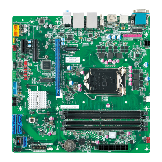
Page 4: Desktop Board Components
Desktop Board Components Figure shows the approximate location of the major components on the top side of MiTAC Desktop Board PH10SU. Figure 1. MiTAC Desktop Board PH10SU Components (Top) - Page 5 TAC D PH10SU C ABLE ESKTOP OARD OMPONENTS HOWN IN THE IGURE Back Panel Connectors RS232 power select header 4-pin Power header CPU Socket CPU FAN header DIMM Sockets Front FAN header ATX Power 24pin header PCIe x16 slot APS header...
-
Page 6: System Memory
Processor The board supports 6th generation Intel Core processors. Other processors may be supported in the future. This board supports processors with a maximum wattage of 91 W Thermal Design Power (TDP). NOTE This board has specific requirements for providing power to the processor. Additional power required will depend on configurations chosen by the integrator. - Page 7 MITAC Desktop Board PH10SU Hardware Specifiction...
- Page 8 1. Platform Definition 1.1 Major Sub-systems 1.1.1 System Memory Board must support the following memory configurations. . • DDR4/-RS 1866MHz to 2133MHz or maximum multiplier supported by the CPU Board must support all DIMMs in this range • 4Gb, 8Gb and 16Gb technology (and any others supported by the processor) •...
-
Page 9: External Graphics
Note: Channel A, DIMM0 must be closest to the CPU. {Closest to CPU} Channel A DIMM0 (DIMM1) A&B Channel A DIMM1 (DIMM2) A&B Channel B DIMM0 (DIMM3) A&B Channel B DIMM1 (DIMM4) A&B Figure 1: Q170 4xDIMMs Connector Layout {Closest to CPU} Channel A DIMM1 (DIMM2) A&B Channel B DIMM1 (DIMM4) - Page 10 The processor will continue to support Silent stream. Silent stream is an integrated audio feature that enables short audio streams, such as system events to be heard over the HDMI* and DisplayPort* monitors. The processor supports silent streams over the HDMI and DisplayPort interfaces at 44.1 kHz, 48 kHz, 88.2 kHz, 96 kHz, 176.4 kHz, and 192 kHz sampling rates.
- Page 11 The following onboard graphics connectors must be supported when onboard graphics is enabled. HD feature: High-Definition Multimedia Interface (HDMI*) • HD – HDMI1.4 flush mount graphics connector: backpanel video • • The High-Definition Multimedia Interface (HDMI*) is provided for transmitting uncompressed digital audio and video signals from DVD players, set-top boxes, and other audio-visual sources to television sets, projectors, and other video displays.
- Page 12 • HDMI includes three separate communications channels: TMDS, DDC, and the optional CEC (consumer electronics control). CEC is not supported on the processor. As shown in the following figure, the HDMI cable carries four differential pairs that make up the TMDS data and clock channels. These channels are used to carry video, audio, and auxiliary data.
- Page 13 • DisplayPort* feature • Display Port: backpanel video (with embedded audio) connector for digital display support up to max resolution allowed by the processor/PCH. Design must be Display Port v1.2 compliant and support the following features: • • Hot-plug detect Display Port Interoperability - to allow use of a Display Port to DVI or Display Port to HDMI dongles as described in the Shark Bay Platform Design Guide...
- Page 14 Hardware Accelerated Video Processing There is hardware support for image processing functions such as De-interlacing, Film cadence detection, Advanced Video Scaler (AVS), detail enhancement, image stabilization, gamut compression, HD adaptive contrast enhancement, skin tone enhancement, total color control, Chroma de-noise, SFC pipe (Scalar...
- Page 15 and Format Conversion), memory compression, Localized Adaptive Contrast Enhancement (LACE), spatial de-noise, Out-Of-Loop De-blocking (from AVC decoder), 16 bpc support for denoise/ de-mosaic. There is support for Hardware assisted Motion Estimation engine for AVC/MPEG2 encode, True Motion, and Image stabilization applications. The HW video processing is exposed by the graphics driver using the following APIs: •...
- Page 16 Signal name Description Front panel microphone input signal (biased when supporting stereo microphone) AUD_GND Ground used by analog audio circuits MIC_BIAS Microphone power / additional MIC input for stereo microphone support Active low signal that signals BIOS that an Intel® HD Audio dongle is connected to the analog header.
- Page 17 • SMBUS/SMLink support for PCH temp • Support for as many fan headers as required in section 1.4.2 - Fan Header Requirements • Support minimum of 2 temperature inputs per PWM Controller for duty cycle determination • Support for non-ACPI based fan control (thermal responsiveness independent of system software) •...
- Page 18 1.2.2 USB Board must support the following Universal Serial Bus ports: Port Summary • 10 total USB2.0 Ports (4 back-panel, 6 internal) • 4 total USB 3.0 Ports (2 back-panel / 2 internal) Implementation Details: • 2 USB v2.0 ports via the back-panel •...
- Page 19 Signal Description IntA_P1_SSTX+ USB3 ICC Port1 SuperSpeed Tx+ Ground IntA_P1_D- USB3 ICC Port1 D- (USB2 Signal D-) IntA_P1_D+ USB3 ICC Port1 D- (USB2 Signal D+) Over Current Protection IntA_P2_D+ USB3 ICC Port2 D+ (USB2 Signal D+) IntA_P2_D- USB3 ICC Port2 D- (USB2 Signal D-) Ground IntA_P2_SSTX+ USB3 ICC Port2 SuperSpeed Tx+...
- Page 20 Signal Signal +5V DC +5V DC Data (negative) Data (negative) Data (positive) Data (positive) Ground Ground Key (no pin) No Connect Table 1: Front panel USB header signals Notes: Front panel USB headers must be placed within a keep-out-zone no smaller than 1 inch (half-inch to the left and half-inch to the right of the header) so as to support commonly available USB connectors.
-
Page 21: Pci Express Expansion Slots
7 LPC Data2 8 LPC Data3 9 Ground 10 Ground 11 VCC3 12 VCC3 13 Key (no pin) 14 VCC3 1.2.4 PCI Express Expansion Slots Board’s PCI Express slot(s) must be PCI Express Specification v2.0 compliant and compatible with PCI Express v2.0 and v1.1 add-in cards. - Page 22 Figure 8: Front panel main header pin-out Signal Name Description Signal Name Description HDD_POWER_LED Pull-up resistor (750Ω) to +5V POWER_LED_MAIN [Out] Front panel LED (main color) HDD_LED# [Out] Hard disk activity LED POWER_LED_ALT [Out] Front panel LED (alt color) GROUND Ground POWER_SWITCH# [In] Power switch...
-
Page 23: Serial Port
1.3.3 MiAPI feature The MiAPI port header must be 2x10, 2.54mm pitch, colored black and keyed at pin 20, as defined in Signal Signal RS232 RS485 RS422 RS232 RS485 RS422 1 DCD (Data Carrier Detect) R(A) / T(A) TX(B) 2 RXD# (Receive Data) R(B) / T(B) TX(A) 3 TXD# (Transmit Data) - Page 24 Table 26. Header must be located around the expansion slots area to minimize port dongle cable length (most are 4” or less). Internal I/O header: Standart 9 pin RS232 or RS485, RS422 port COM port 3; COM port 4 Figure 10: Serial port header pin-out Signal Signal RS232...
- Page 25 Figure 51: RS232 Serial port pin-out DTE Signal DTE Signal DTE Signal DTE Signal Signal Signal Signal Signal Signal Name Signal Name Signal Name Signal Name direction direction direction direction 1 DCD Data Carrier Detect 2 RXD Receive Data 3 TXD Transmit Data 4 DTR Data Terminal Ready...
- Page 26 Pin1 can select 12V / GND/ RS232: NDCD at J24 and J26 Pin1 12V: J24.2<=>J24.4 J26.2<=>J26.4 Pin1 GND: J24.6<=>J24.4 J26.6<=>J26.4 Pin1 NDCD: J24.3<=>J24.4 J26.3<=>J26.4 Pin9 can select 12V/ 5V / RS232: NRI at J25 and J27 Pin9 12V: J25.2<=>J25.4 J27.2<=>J27.4 Pin9 5V: J25.6<=>J25.4 J27.6<=>J27.4...
- Page 27 1.3.5 Parallel Port The parallel port header must be 2x13, 2.54mm pitch, colored pink (Pantone color code “Rhodamine Red C”) and keyed at pin 26, as defined in Figure 62 and Table9. Header must be located around the expansion slots area to minimize port dongle cable length.
- Page 28 1.4 Thermal Management and Fan Control • Nuvoton NCT6104D SuperIO: backup alternate solution as it leverages existing hardware in the designs, but software infrastructure must be put in place to support this solution. Regardless of solution chosen, BIOS/driver/tools support and subsystem validation is required, even if solution is not needed by pilot.
- Page 29 Figure 84: Front/Rear fan header 1.4.2 Fan Header Requirements The below requirements must be met for the 4-pin processor/heatsink fan (CPU FAN) header: • Closed loop fan speed control via the FANPWM0 signal routed to pin-4 • Route fan tachometer signal to FANTACH0 input •...
- Page 30 Silkscreen labels should be white back-ground with clear text: . • ATX board must have expansion slots clearly labeled as follows: PCIe x16 (PCIE_X16_SLOT1) PCIe M2 Key-M (J_M2_KM_1) PCIe x4 (PCIE_X4_SLOT1) PCIe x1 (PCIE_X1_SLOT1) • SATA ports from PCH SATA controller must be clearly labeled: SATA 0 / SATADOM SATA 1 SATA 2...
- Page 31 FP COM P3 (COM3 location) FP COM P4 (COM4 location) • PS/2 port header must be clearly labeled: None • Chassis intrusion detection header must be clearly labeled: INTRD (J_INTRD1 location) • VR Hot LED must be clearly labeled: None •...
Need help?
Do you have a question about the PH10SU and is the answer not in the manual?
Questions and answers