Table of Contents
Advertisement
Quick Links
Advertisement
Table of Contents

Related Manuals for MiTAC PD11KS


Summary of Contents for MiTAC PD11KS
- Page 1 MITAC 3.5” SBC M/B PD11KS Product Guide...
-
Page 2: Desktop Board Features
Desktop Board Features This chapter briefly describes the features of 3.5” SBC M/B PD11KS. Table 1 summarizes the major features of the M/B Feature Summary MECHANICAL FORM FACTOR 3.5" SBC Embedded: 4” x 5.8” (102mm x 147mm) SYSTEM Intel ®... - Page 3 10% ~ 95% R/H, non-condensing CERTIFICATION CE & FCC KBL: Windows 10 64bit, Linux (support by request) OS SUPPORT SKL: Windows 7 32/64bit, Windows 8.1 64bit, Windows 10 64bit, Linux (support by request) 1. MITAC D PD11KS F ABLE ESKTOP OARD EATURES...
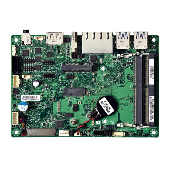
- Page 4 3.5” SBC M/B Components Figure 1 shows the approximate location of the major components on the top side of MITAC 3.5” SBC M/B PD11KS. FIGURE 1. MITAC 3.5” SBC M/B COMPONENTS...
- Page 5 TABLE 2. MITAC 3.5” SBC M/B COMPONENT LIST (SHOWN IN FIGURE 1)
-
Page 6: System Memory
Processor The board supports 6th generation Intel Core processors. Other processors may be supported in the future. This board supports processors with a maximum wattage of 65 W Thermal Design Power (TDP). NOTE This board has specific requirements for providing power to the processor. Additional power required will depend on configurations chosen by the integrator. - Page 7 Dual RJ45 Connector Diagram LED Color State Condition LAN link is not established LAN link is Link established Green LAN activity Blinking occurring 10 Mb/s data rate Figure 1 LAN Connector (2D)▲ Green 100 Mb/s data rate Speed Yellow 1000 Mb/s data rate Table 3: RJ45 LED behavior ▲...
- Page 8 Table 4: LVDS/ eDP Connector pin definition ▼ LVDS Define eDP Define LVDS0_LINK3_CON_DP LVDS0_LINK3_CON_DN LVDS0_LINK2_CON_DP eDP_TX3_DN LVDS0_LINK2_CON_DN eDP_TX3_DP LVDS0_LINK1_CON_DP LVDS0_LINK1_CON_DN eDP_TX2_DN LVDS0_LINK0_CON_DP eDP_TX2_DP LVDS0_LINK0_CON_DN LVDS1_LINK3_CON_DP eDP_TX1_DN LVDS1_LINK3_CON_DN eDP_TX1_DP LVDS1_LINK2_CON_DP LVDS1_LINK2_CON_DN eDP_TX0_DN LVDS1_LINK1_CON_DP eDP_TX0_DP LVDS1_LINK1_CON_DN LVDS1_LINK0_CON_DP eDP_AUX_DN LVDS1_LINK0_CON_DN eDP_AUX_DP Panel VDD Panel VDD Panel VDD Panel VDD...
- Page 9 LVDS1_CLK_CON_DP LVDS1_CLK_CON_DN Backlight VCC Backlight VCC Backlight VCC Backlight VCC DDC_SDA External Speaker Socket) Figure 3: External Speaker Socket (2D) ▼ Table 5: External Speaker Socket pin definition ▼ Pin Signal Name Description +12V LINE OUT L [Out] Lift channel LINE OUT R [Out] Right channel Ground...
- Page 10 Internal Speaker Socket) Figure 4: Internal Speaker Socket (2D)▲ Table 6: Internal Speaker Socket pin definition ▼ Pin Signal Name Description LINE OUT L- [Out] Lift channel- LINE OUT L+ [Out] Lift channel+ LINE OUT R- [Out] Right channel- LINE OUT R+ [Out] Right channel + SATA Power Socket) Figure 5: SATA Power Socket (2D) ▼...
-
Page 11: Power Button
MiAPI Socket) Figure 6: MiAPI Socket (2D)▼ MAPI_GPIO1 MAPI_GPIO2 MAPI_GPIO6 MAPI_GPIO3 MAPI_GPIO7 MAPI_GPIO4 MAPI_GPIO8 MAPI_GPIO5 MAPI_GPIO9 WD_Time MAPI_GPIO10 Power Button SMBUS_DATA UART_TX SMBUS_CLK UART_RX 5VSB Table 8: MiAPI Socket pin definition ▲ DC IN Power Socket) Pin Signal Name Description [IN] 8~24V [IN] 8~24V Ground... - Page 12 FAN Socket) Pin Signal Name Description Ground [Out] 12V CPU_FAN_TACH FAN speed detect CPU_FAN_CTRL FAN speed control Table 10: External Speaker Socket pin definition )▲ Panel Backlight Control Cable Socket) Figure 7: Backlight control cable Socket (2D)▲ Pin Signal Name Description BKTL_EN [Out] Lift channel-...
- Page 13 COM Port Header) Figure 8: RS232 COM Port Header (2D)▲ Table 12: RS232 COM Port pin definition ▲ Note. H4 COM port support RS422 & RS485 by BIOS setting.
- Page 14 Front Panel Header) Pin Signal Name Description Pin Signal Name Description Pull-up resistor (510Ω) to [Out] Front panel LED (main HDD_POWER_LED POWER_LED_MAIN color) [Out] Hard disk activity [Out] Front panel LED (alt HDD_LED# POWER_LED_ALT color) GROUND Ground POWER_SWITCH# [In] Power switch RESET_SWITCH# [In] Reset switch GROUND...
- Page 15 Pin Signal Name Description No Pin VCC3 +12V PANEL_PWR [Out] output panel power No Pin Table 14: Panel Power selection header pin definition ▲ Panel Backlight Power Selection Header) Pins 1&2: jumper position for +12V mode Pins 2&3: jumper position for +5V mode Pin Signal Name Description +12V...
-
Page 16: Pin Signal
Dual USB2.0 Header) Figure 10: Dual USB2.0 header pin-out Pin Signal Pin Signal +5V DC +5V DC Data (negative) Data (negative) Data (positive) Data (positive) Ground Ground Key (no pin) No Connect Table 16: Dual USB2.0 header pin definition ▲ AT/ATX Mode Selection Header) Pins 1&2: jumper position for AT mode... - Page 17 Pin Signal Name Description PSON_AT_N Power on signal SW_PWRBT_N Power switch signal No connection Table 17: Panel Power selection header pin definition ▲ CMOS Clear Header) Pins 1&2: Normal Pins 2&3: jumper position for CMOS Reset CMOS Clear Clear CMOS Normal Table 18: CMOS Clear behavior ▲...
-
Page 18: Bios Specification
MITAC 3.5” SBC M/B PD11KS BIOS Specification... - Page 19 MAIN PAGE Main Advanced Chipset Security Boot Save & Exit Item help BIOS Information BIOS Vender American Megatrends Core Version 5.12 Compliancy UEFI 2.6 ; PI 1.4 BIOS Version D7760A01 Build Date 04/21/2017 ME FW Version 11.8.50.3399 Processor Information Intel(R) CORE(TM) i5-7300U CPU @ 2.60GHz Memory Information Total Memory 32768 MB...
- Page 20 Comment This field is not selectable. There is no help text associated with it. Field Name Build Date Default Value Display build date of the BIOS Comment This field is not selectable. There is no help text associated with it. Field Name ME FW Version Value...
-
Page 21: Advanced Page
ADVANCED PAGE Main Advanced Chipset Security Boot Save & Exit ►CPU Configuration Item help ►Trusted Computing ►ACPI Settings ►SMART Settings ►Super IO Configuration ►Hardware Monitor →←: Select Screen ►S5 RTC Wake Settings ↑↓: Select Item ►Network Stack Configuration Enter: Select +/- : Change Opt F1: General Help F2: Previous Values... - Page 22 Help Monitor hardware status Comment Press Enter when selected to go into the associated Sub-Menu. Field Name S5 RTC Wake Settings Help Enable system to wake from S5 using RTC alarm. Comment Press Enter when selected to go into the associated Sub-Menu. Field Name Network Stack Configuration Help...
-
Page 23: Cpu Configuration
CPU CONFIGURATION Main Advanced Chipset Security Boot Save & Exit Item help CPU Configuration Type Intel(R) Core(TM) CPU i5-7300U @ 2.60 GHz 0x806E9 Speed 2700 MHz L1 Data Cache 32 KB x 2 L1 Code Cache 32 KB x 2 L2 Cache 256 KB x 2 L3 Cache... - Page 24 Field Name L1 Data Cache Default Value L1 Data Cache Size Comment This field is not selectable. There is no help text associated with it. Field Name L1 Code Cache Default Value L1 Code Cache Size Comment This field is not selectable. There is no help text associated with it. Field Name L2 Cache Default Value...
- Page 25 Possible Value Enabled Disabled Help Enabled for Windows XP and Linux (OS optimized for Hyper-Threading Technology) and Disabled for other OS (OS not optimized for Hyper- Threading Technology). Field Name Intel Trusted Execution Technology Default Value [Disabled] Possible Value Enabled Disabled Help Enables utilization of additional hardware capabilities provided by Intel...
-
Page 26: Trusted Computing
TRUSTED COMPUTING (OPTIONAL) Main Advanced Chipset Security Boot Save & Exit Item help TPM20 Device Found Vender : NTC Firmware Version: 1.3 Security Device Support [Enable] →←: Select Screen Pending operation [None] ↑↓: Select Item TPM2.0 UEFI Spec Version [TCG_2] Enter: Select +/- : Change Opt F1: General Help... -
Page 28: Acpi Settings
ACPI SETTINGS Main Advanced Chipset Security Boot Save & Exit Item help ACPI Settings →←: Select Screen Enable ACPI Auto Configuration [Disabled] ↑↓: Select Item Enable Hibernation [Enabled] Enter: Select ACPI Sleep State [S3 (Suspend to RAM)] +/- : Change Opt F1: General Help F2: Previous Values F3: Optimized Defaults... -
Page 29: Smart Settings
SMART SETTINGS Main Advanced Chipset Security Boot Save & Exit Item help SMART Settings →←: Select Screen SMART Self Test [Disabled] ↑↓: Select Item Enter: Select +/- : Change Opt F1: General Help F2: Previous Values F3: Optimized Defaults F4: Save & Reset ESC: Exit Version 2.18.1264. -
Page 30: Super Io Configuration
SUPER IO CONFIGURATION Main Advanced Chipset Security Boot Save & Exit SIO Configuration Item help ►Serial Port 1 Configuration →←: Select Screen ►Serial Port 2 Configuration ↑↓: Select Item ►Serial Port 3 Configuration Enter: Select ►Serial Port 4 Configuration +/- : Change Opt F1: General Help F2: Previous Values F3: Optimized Defaults... - Page 31 Serial Port 1 Configuration Main Advanced Chipset Security Boot Save & Exit Serial Port 1 Configuration Item help →←: Select Screen Serial Port [Enabled] ↑↓: Select Item Device Settings IO=3E8h; IRQ=7; Enter: Select +/- : Change Opt Change Settings [Auto] F1: General Help F2: Previous Values F3: Optimized Defaults...
- Page 32 Serial Port 2 Configuration Main Advanced Chipset Security Boot Save & Exit Serial Port 2 Configuration Item help →←: Select Screen Serial Port [Enabled] ↑↓: Select Item Device Settings IO=2E8h; IRQ=5; Enter: Select +/- : Change Opt Change Settings [Auto] F1: General Help Mode Configuration [3T/5R RS232]...
- Page 33 Disabled Help Configure serial port as RS232/RS422/RS485.
- Page 34 Serial Port 3 Configuration Main Advanced Chipset Security Boot Save & Exit Serial Port 3 Configuration Item help →←: Select Screen Serial Port [Enabled] ↑↓: Select Item Device Settings IO=3F8h; IRQ=4; Enter: Select +/- : Change Opt Change Settings [Auto] F1: General Help F2: Previous Values F3: Optimized Defaults...
- Page 35 Serial Port 4 Configuration Main Advanced Chipset Security Boot Save & Exit Serial Port 4 Configuration Item help →←: Select Screen Serial Port [Enabled] ↑↓: Select Item Device Settings IO=2F8h; IRQ=3; Enter: Select +/- : Change Opt Change Settings [Auto] F1: General Help F2: Previous Values F3: Optimized Defaults...
-
Page 36: Hardware Monitor
HARDWARE MONITOR Main Advanced Chipset Security Boot Save & Exit PC Health Status Item help : xx °C →←: Select Screen CPU temperature : xx °C ↑↓: Select Item CPU VR temperature : xx °C DIMM temperature Enter: Select Fan Speed : xxxx RPM +/- : Change Opt 1V StandBy... - Page 37 S5 RTC WAKE SETTINGS Main Advanced Chipset Security Boot Save & Exit Wake system from S5 [Disabled] Item help Wake up hour Wake up minute Wake up second →←: Select Screen ↑↓: Select Item Enter: Select +/- : Change Opt F1: General Help F2: Previous Values F3: Optimized Defaults...
- Page 38 Field Name Wake up second(Show when Wake system from S5 set to Fixed Time) Default Value Possible Value 0 - 59 Help 0 - 59...
-
Page 39: Network Stack Configuration
NETWORK STACK CONFIGURATION Main Advanced Chipset Security Boot Save & Exit Item help Network stack [Disabled] →←: Select Screen Ipv4 PXE Support [Disabled] ↑↓: Select Item Ipv6 PXE Support [Disabled] Enter: Select +/- : Change Opt F1: General Help F2: Previous Values F3: Optimized Defaults F4: Save &... -
Page 40: Chipset Page
CHIPSET PAGE Main Advanced Chipset Security Boot Save & Exit ►System Agent (SA) Configuration Item help ►PCH-IO Configuration →←: Select Screen ↑↓: Select Item Enter: Select +/- : Change Opt F1: General Help F2: Previous Values F3: Optimized Defaults F4: Save & Reset ESC: Exit Version 2.18.1264. -
Page 41: System Agent (Sa) Configuration
SYSTEM AGENT (SA) CONFIGURATION Main Advanced Chipset Security Boot Save & Exit Item help System Agent (SA) Configuration ►Memory Configuration ►Graphics Configuration →←: Select Screen ↑↓: Select Item Enter: Select +/- : Change Opt F1: General Help F2: Previous Values F3: Optimized Defaults F4: Save &... - Page 42 Memory Configuration Main Advanced Chipset Boot Security Save & Exit Item help Memory Configuration →←: Select Screen Memory Frequency 2133 Mhz ↑↓: Select Item DIMM#1 16384 MB (DDR4) DIMM#2 16384 MB (DDR4) Enter: Select +/- : Change Opt F1: General Help F2: Previous Values F3: Optimized Defaults F4: Save &...
- Page 43 Graphics Configuration Main Advanced Chipset Security Boot Save & Exit Item help Graphics Configuration →←: Select Screen DVMT Pre-Allocated [32M] ↑↓: Select Item DVMT Total Gfx Mem [256M] Enter: Select +/- : Change Opt F1: General Help F2: Previous Values F3: Optimized Defaults F4: Save &...
-
Page 44: Pch-Io Configuration
PCH-IO CONFIGURATION Main Advanced Chipset Security Boot Save & Exit Item help PCH-IO Configuration ►HD Audio Configuration →←: Select Screen ↑↓: Select Item DeepSx Power Policies [Disabled] Enter: Select Wake On LAN [Enabled] +/- : Change Opt State After G3 [S5 State] F1: General Help F2: Previous Values... - Page 45 HD Audio Configuration Main Advanced Chipset Boot Security Save & Exit Item help HD Audio Subsystem Configuration Settings HD Audio [Auto] →←: Select Screen ↑↓: Select Item Enter: Select +/- : Change Opt F1: General Help F2: Previous Values F3: Optimized Defaults F4: Save &...
-
Page 46: Security Page
SECURITY PAGE Main Advanced Chipset Security Boot Save & Exit Item help Password Description If Only the Administrator's password is set, then this only limits access to Setup and is only asked for when entering Setup. If ONLY the User’s password is set, then this is a power on password and must be entered to boot or enter Setup. - Page 47 Field Name Secure Boot Help Customizable Secure Boot settings Comment Press Enter when selected to go into the associated Sub-Menu. Field Name Secure Flash Update Help Secure Flash Update support Comment Press Enter when selected to go into the associated Sub-Menu.
-
Page 48: Hdd Security
HDD SECURITY Main Advanced Chipset Security Boot Save & Exit Item help HDD Password Description : Allows Access to Set, Modify and Clear HardDisk User and Master Passwords. User Password need to be installed for Enabling Security. Master Password can be Modified only when successfully unlocked with Master Password in POST. -
Page 49: Secure Boot
SECURE BOOT Main Advanced Chipset Security Boot Save & Exit Item help System Mode Setup Vender keys Not Modified →←: Select Screen Secure Boot Enable [Disabled] ↑↓: Select Item Not Active Enter: Select Secure Boot Mode [Custom] +/- : Change Opt F1: General Help ►... - Page 50 Help Delete NVRAM content of all UEFI Secure Boot key databases...
-
Page 51: Enroll Efi Image
Key Management Main Advanced Chipset Security Boot Save & Exit Item help Factory Key Provision [Disabled] ► Restore Factory Keys ► Reset To Setup Mode ► Export Secure Boot variables ► Enroll Efi Image ► Device Guard ready ► Remove ‘UEFI CA’ from DB →←: Select Screen ►... - Page 52 system device Field Name Enroll Efi Image Help Allow the image to run in Secure Boot mode. Enroll SHA256 Hash certificate of a PE image into Authorized Signature Database (db) Remove ‘UEFI CA’ from DB Field Name Help Device Guard ready system must not list 'Microsoft UEFI CA' Certificate in Authorized Signature database (db) Field Name Remove DB defaults...
- Page 53 c)EFI_CERT_RSA2048 (bin) d)EFI_CERT_SHA256,384,512 2.Authenticated UEFI Variable 3.EFI PE/COFF Image(SHA256) Key Source: Factory,External,Mixed comment Press Enter when selected to go into the associated Sub-Menu. Field Name Forbidden Signature Default Value Size:0, Key#:0, Key source: No Key Help Enroll Factory Defaults or load certificates from a file: 1.Public Key Certificate in: a)EFI_SIGNATURE_LIST b)EFI_CERT_X509 (DER encoded)
-
Page 55: Secure Flash Update
SECURE FLASH UPDATE Main Advanced Chipset Security Boot Save & Exit ►Path for ROM Image Item help Notice : →←: Select Screen ROM Image must in the root folder of storage device. ↑↓: Select Item File name must match with current BIOS project. Enter: Select +/- : Change Opt F1: General Help... -
Page 56: Fixed Boot Order Priorities
BOOT PAGE Main Advanced Chipset Security Boot Save & Exit Item help Boot Configuration Setup Prompt Timeout Bootup NumLock State [On] Boot Mode Select [UEFI] →←: Select Screen FIXED BOOT ORDER Priorities ↑↓: Select Item Boot Option #1 [USB Floppy] Boot Option #2 [USB CD/DVD] Enter: Select... - Page 57 Field Name Boot Mode Select Default Value [UEFI] Possible Value LEGACY (Support Skylake series for Win7) UEFI Help Select boot mode LEGACY/UEFI Field Name Boot Option #1 Default Value [USB Floppy] Possible Value Hard Disk, USB Hard Disk, USB CD/DVD, USB Key, USB Floppy , USB Lan, Network Help Sets the system boot order...
- Page 58 Help Sets the system boot order Field Name (UEFI) USB Floppy Drive BBS Priorities Help Specifies the Boot Device Priority sequence from available USB Floppy Drives. Comment Press Enter when selected to go into the associated Sub-Menu. Field Name (UEFI) USB CD/DVD ROM Drive BBS Priorities Help Specifies the Boot Device Priority sequence from available USB CDROM/DVD Drives.
- Page 59 (LIST BOOT DEVICE TYPE) DRIVE BBS PRIORITIES Main Advanced Chipset Security Boot Save & Exit Item help Boot Option #1 [Boot Device Name 1] Boot Option #2 [Boot Device Name 2] →←: Select Screen ↑↓: Select Item Enter: Select +/- : Change Opt F1: General Help F2: Previous Values F3: Optimized Defaults...
-
Page 60: Save & Exit Page
SAVE & EXIT PAGE Main Advanced Chipset Security Boot Save & Exit Item help Save Options Discard Changes and Exit Save Changes and Reset Discard Changes and Reset Restore Defaults →←: Select Screen ↑↓: Select Item Enter: Select +/- : Change Opt F1: General Help F2: Previous Values F3: Optimized Defaults... -
Page 61: Reset Nvram
RECOVERY PAGE (ACTIVE FOR SECURE FLASH UPDATE ONLY) Main Advanced Chipset Security Boot Save & Exit Recovery Item help Please select block you want to update Reset NVRAM [Disabled] ►Process with flash update →←: Select Screen ↑↓: Select Item Enter: Select +/- : Change Opt F1: General Help F2: Previous Values...
Need help?
Do you have a question about the PD11KS and is the answer not in the manual?
Questions and answers