Table of Contents
Advertisement
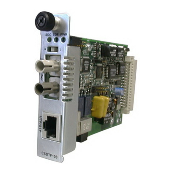
User's Guide
CSDTF10xx-10x
Slide-in-Module Devices
• T1 / E1 with Remote Management
• Copper to Fiber
Transition Networks CSDTF10xx-10x series Devices, designed
to be installed into the Transition Networks PointSystem™
chassis, encode and decode T1 or E1 twisted-pair copper
signals over fiber optic cable to extend the distance and
transmission reliability of high-speed T1 or E1 data traffic. The
device is framing independent (as ESF vs. D4) and supports all common line codes (e.g.,
AMI, B8ZS, HDB3).
The CSDTF10xx-10x is designed to be installed in pairs. For example, install one
CSDTF1011-105 as the "local" Device and another CSDTF1011-105 as the "remote"
Device.
Part Number
Port One - Copper
CSDTF1011-105
RJ-45
1.5 km (5,000 feet) *
CSDTF1012-105
RJ-45
1.5 km (5,000 feet) *
CSDTF1013-105
RJ-45
1.5 km (5,000 feet) *
CSDTF1014-105
RJ-45
1.5 km (5,000 feet) *
CSDTF1015-105
RJ-45
1.5 km (5,000 feet) *
CSDTF1016-105
RJ-45
1.5 km (5,000 feet) *
CSDTF1017-105
RJ-45
1.5 km (5,000 feet) *
CSDTF1018-105
RJ-45
1.5 km (5,000 feet) *
CSDTF1022-105
RJ-45
1.5 km (5,000 feet) *
CSDTF1025-105
RJ-45
1.5 km (5,000 feet) *
CSDTF1027-105
RJ-45
1.5 km (5,000 feet) *
* Typical maximum cable distance. Actual
distance is dependent upon the physical
characteristics of the network
Note: The CSDTF10xx-10x requires a CSU
between theDevice and the Public
Telephone Network.
Port Two - Duplex Fiber-Optic
ST, 850 nm multimode
2 km (1.2 miles)*
ST, 1310 nm single mode
8 km (4.8 miles)*
SC, 850 nm multimode
2 km (1.2 miles)*
SC, 1310 nm single mode
20 km (12.4 miles)*
SC, 1310 nm single mode
40 km (24.8 miles)*
SC, 1310 nm single mode
60 km (37.3 miles)*
SC, 1550 nm single mode
80 km (49.7 miles)*
MT-RJ, 1300 nm multimode
2 km (1.2 miles)*
ST, 1310 nm single mode
15 km (9.3 miles)*
MT-RJ, 1310 nm single mode
20 km (12.4 miles)*
ST, 1300 nm multimode
5 km (3.1 miles)*
Installation . . . . . . . . . . . . . . . . . . . . .3
Operation . . . . . . . . . . . . . . . . . . . . . .9
Cable Specifications . . . . . . . . . . . . .10
Technical Specifications . . . . . . . . . .12
Troubleshooting . . . . . . . . . . . . . . . .13
Compliance Information . . . . . . . . .16
Advertisement
Table of Contents

Subscribe to Our Youtube Channel
Related Manuals for Transition Networks CSDTF1011-105


Summary of Contents for Transition Networks CSDTF1011-105
- Page 1 (as ESF vs. D4) and supports all common line codes (e.g., AMI, B8ZS, HDB3). The CSDTF10xx-10x is designed to be installed in pairs. For example, install one CSDTF1011-105 as the “local” Device and another CSDTF1011-105 as the “remote” Device. Part Number...
-
Page 2: Installation
CSDTF10xx-10x Part Number Port One - Copper Port Two - Single Fiber Optic CSDTF1029-105 ** RJ-45 SC, 1310 mn (TX)/1550 nm (RX) 1.5 km (5,000 feet) * single mode, 20 km (12.4 miles)* CSDTF1029-106 ** RJ-45 SC, 1550 mn (TX)/1310 nm (RX) 1.5 km (5,000 feet) * single mode, 20 km (12.4 miles)* CSDTF1029-107 *** RJ-45... - Page 3 CSDTF10xx-10x Installation -- Continued Set the loop-back switch Hardware mode: The loop-back switch is located on the front panel of the Device and is used for installation and network debugging procedures. To set the switch, use a small flat-blade screwdriver or a similar device (see the drawing to the right).
-
Page 4: Install The Slide-In-Module
CSDTF10xx-10x Installation -- Continued T1/short-haul signal Use switches 3 and 4 on the left switch set to select T1/short-haul signal (see the drawing below). Use switches 1, 2 and 3 on the right switch set to select the proper network cable settings. -
Page 5: Operation
CSDTF10xx-10x Installation -- Continued Install the copper cable Locate or build twisted-pair copper cables that are compliant with the specifications on page 11 with RJ-45 connectors at both ends. Ensure that the MDI/MDI-X switch is set according to the network conditions (see page 3). -
Page 6: Cable Specifications
Fiber Cable single mode fiber (recommended): 9 µm Multimode fiber (recommended): 62.5/125 µm Multimode fiber (optional): 100/140, 85/140, 50/125 µm CSDTF1011-105 850 nm multimode Fiber Optic Transmitter Power: min: -19.0 dBm Fiber Optic Receiver Sensitivity: min: -32.5 dBm Link Budget: 13.5 dB... -
Page 7: Technical Specifications
CSDTF10xx-10x Technical Specifications For use with Transition Networks Model CSDTF10xx-10x or equivalent Standards: Emissions: CISPR A; Telecordia TR-NWT-001089 (designed to meet; NOT tested); FCC Part 68; T1/E1 Physical layer: ITU-T, ANSI, AT&T, and ETSI; European Technical Standard: TBR 12; British Technical Publication: PD 7024 : 1994 (NTR 4) Dimensions: 3.4"... - Page 8 952-941-7600 800-526-9267 952-941-2322 Declaration of Conformity Transition Networks 10900 Red Circle Drive, Minnetonka MN 55343 U.S.A. CSDTF10xx-10x Series Devices CSDTF1011-105, CSDTF1012-105, CSDTF1013-105, CSDTF1014-105, CSDTF1015-105, CSDTF1016-105, CSDTF1017-105, CSDTF1018-105, CSDTF1022-105, CSDTF1025-105, CSDTF1027-105, CSDTF1029-105, CSDTF1029-106, CSDTF1029-107, CSDTF1029-108 EMC Directive 89/336/EEC September, 2008 Date...
-
Page 9: Compliance Information
CSDTF10xx-10x Compliance Information CISPR22/EN55022 Class A + EN55024 CE Mark FCC regulations This equipment has been tested and found to comply with the limits for a Class A digital device, pursuant to part 15 of the FCC rules. These limits are designed to provide reasonable protection against harmful interference when the equipment is operated in a commercial environment.
Need help?
Do you have a question about the CSDTF1011-105 and is the answer not in the manual?
Questions and answers