Table of Contents
Advertisement
Advertisement
Table of Contents

Related Manuals for Xylem OMNI sensus C2


Summary of Contents for Xylem OMNI sensus C2
- Page 1 OMNI C2, F2, R2 and T2 Meters User Guide WUG-10003-04...
- Page 2 Information in this Document is subject to change without notice and does not represent a commitment on the part of Sensus. © 2021, Sensus USA, Inc., a subsidiary of Xylem, Inc. All Rights Reserved. Sensus, the Sensus logo, FlexNet ®...
-
Page 3: Table Of Contents
Contents 1 OMNI™ meter overview........... 4 OMNI™+ register.................. 4 Alarms....................4 Data logging..................4 OMNI meter specifications..............4 2 LCD display............... 6 Segment Test view................. 6 Totalizer view..................7 Flow direction indicator................8 Notification view..................8 Smart Mode and Normal Mode............8 Notification icons................9 Battery icon.................... -
Page 4: Omni™ Meter Overview
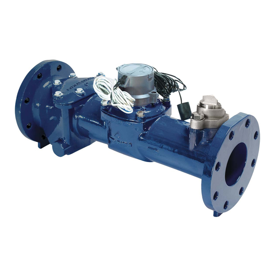
1 OMNI™ meter overview OMNI water meters feature unrestricted sustained flow rates within their continuous operating range. The OMNI meter's Floating Ball Technology (FBT) measuring element operates virtually without friction or wear. Each OMNI meter consists of two basic assemblies: the maincase and the measuring chamber. - Page 5 Category Specification Contact Open Duration User selectable fixed 5, 10, 20, 50, 200, 500 ms or dynamic with a 32 ms Minimum (at 16Hz output)² Duty Cycle Approx. 50/50 ± 20% at normal flow rates Pull-up Resistor (when required) 6000 Ohms Pulse Cable Length 25 ft.
-
Page 6: Lcd Display
2 LCD display The LCD is the visual reporting mechanism for the meter. The display contains dedicated display areas for information and icons. Multiple views are available; use the lid to toggle through the various views. The first view available when opening the lid is the Segment Test view. -
Page 7: Totalizer View
Totalizer view The accumulation displays digits and decimal points. The units of measurement display in the lower-left corner of the LCD. The Totalizer view displays consumption values or messages, AMI/AMR digit identifier bars, the unit of measure, the flow direction, and any notification icons that are currently active. -
Page 8: Flow Direction Indicator
Flow direction indicator The LCD displays a flow direction indicator at the lower right. A circle containing a "+" represents a positive flow while a circle containing a "-" represents a negative flow. If no circle is present, there is no flow or the flow is so minimal it cannot be detected. Notification view The Notification view provides more information about any alarms or events that have been triggered. -
Page 9: Notification Icons
Notification icons Two notification icons display in the upper-right corner of the LCD (in all views) when the applicable conditions are present. The Bell icon represents an Active event or alarm. Active events occur when the device detects that the meter is currently in this event. As long as the meter is in this event, the bell icon remains visible. - Page 10 The NFC antenna is located around the perimeter of the LCD. The NFC tag can be read by placing a compatible device such as a NFC enabled iPhone or Android parallel with the register face. In addition, the device's NFC antenna must be aligned with the center of the OMNI+ LCD.
- Page 11 Tap the phone against the NFC tag near the LCD. The following screen displays, showing the fields that are stored in the NFC tag. 2 LCD display | 11...
- Page 12 The PV field displays the firmware version, the FI field displays the factory identification, and the CI field displays the customer identification. The latest volume reading displays in the V field and the D field displays the date and time of the last reading. The remaining fields contain diagnostic information that Sensus Technical Services may request.
-
Page 13: Signal Connections
3 Signal connections The OMNI+ registers use fully solid-state electronics. The OMNI+ C2/F2/T2 register is available with an optional programmable digital pulse signal suited for interfacing with ACT-PAK instruments and SCADA systems to achieve a 4 to 20 mA output. The OMNI+ R2 register outputs a programmable (using a Sensus FieldLogic Communicator) register ID and AMR reading digits. - Page 14 Illustration 2 Illustration 2 is used for all instruments with internal pull-up resistors. The voltage supplied by the instrument's input when not connected to any circuitry should not exceed 24 Vdc nom. and must not exceed 30 Vdc max. Otherwise, it will overload the MOSFET inside the OMNI+ register.
- Page 15 Illustration 4 Vinstrument Vsupply/2 Vsupply/3 6.8k ~Vsupply/8 The table and formula are valid under the assumption that the instrument's input resistance is higher than 50 kOhms. Otherwise, Vinstrument will be lower than shown in the table or calculated with the formula. *If possible, the circuit of Illustration 2 should be used.
-
Page 16: Omni Installation
4 OMNI installation Required tools Correct tools for the corresponding size of bolts that are used. In the case of the R2, 5/8" bolts are used for the 1-1/2" R2 and ¾" bolts are used for the 2" R2. Depending on the weight of the meter and the installation conditions, hosting devices may be required. - Page 17 5. OMNI meters can be installed vertically or rotated on the bolt pattern in any orientation. Contact Sensus with any questions. 6. No mechanical stresses should be exerted on the meter when installed in the pipeline. The pipeline flanges must align with the meter flanges, the distance between the flanges must match the meter body length, and the weight of the meter must be supported evenly.
-
Page 18: Measuring Chamber
5 Measuring chamber The measuring chamber can be removed and disassembled when required to do so. This section describes the steps for doing so. Note: If the meter is under pressure, pressure must be turned off and relieved before chamber bolts are loosened or removed! Required tools 2.5, 3, and 6mm hex head ball end drivers (6mm not needed for the R2) Sensus seal screw tool—for bonnet removal... -
Page 19: Remove The Measuring Chamber
Remove the measuring chamber Chamber Cover Chamber Cover Bolts Bolt Washers (Black nylon washers are below the stainless steel washers) Chamber Cover Measuring Chamber Chamber Cover O-Ring Note: Chamber Bolt quantity varies by meter size 1. With the service line pressure off, loosen all chamber cover bolts. 2. - Page 20 Note: If the pipe pressure is not relieved yet, water will spray out when the retaining nut is two turns from complete removal. When re-installing, use fingers only and check for leaks before installing the bonnet. 5. Place the register assembly in a safe place. 6.
- Page 21 OMNI+ register 5 Measuring chamber | 21...
- Page 22 Original OMNI register No longer available 5 Measuring chamber | 22...
-
Page 23: Exchange The Measuring Insert
Exchange the measuring insert 1. Before the installation of a replacement measuring insert, the inside surface of the body, especially the seating areas of the O-ring, must be checked for damage. If damaged, a new O-ring must be used. 2. The O-ring and the lip seal must be lubricated with grease approved for use with potable water before installation in to the meter body. -
Page 24: Two-Way Smartpoint Modules
6 Two-way SmartPoint modules This section describes how to use FieldLogic Tools to activate, deactivate, configure, and view the parameter settings of a two-way SmartPoint module. It also covers how to enable an unused port. Activate two-way SmartPoint modules Note: If the configuration's GPS source is set to Required for all SmartPoints and the field device has no GPS fix, the SmartPoint will not be activated. - Page 25 5. Start the FieldLogic Tools application. 6. From the Connect screen, enter the FlexNet ID of the SmartPoint module (using the keypad or bar code scanner,) and select Start Connection. 7. Check the CL's LEDs. Be sure the blue LNK LED is illuminated, indicating a Bluetooth connection between the field device and CL.
- Page 26 11. If prompted, select the applicable product configuration. 12. If activating a pit unit, you are prompted to complete the physical installation. 13. Remove the CommandLink from the bottom of the SmartPoint module. Important: Return the pit lid and attached SmartPoint module to its final position over the meter pit to ensure that FlexNet settings are properly configured.
- Page 27 Note: The product configuration names listed will vary depending on the product configuration in use. You should ask your supervisor (or Sensus representative) for guidance on the applicable product configuration to choose. Note: If no matching configurations are present, an error displays. Select OK to return to the Product Summary screen.
-
Page 28: Fieldlogic Errors
FieldLogic errors This section describes some of the most common errors that you may encounter while using FieldLogic Tools and suggests possible corrective actions. Activation errors If SmartPoint module activation fails, FieldLogic Tools may display an error message. The following table lists common activation errors along with possible causes and corrective actions. - Page 29 Common Activation Errors Error Message Possible Cause Corrective Action Communication failure: SmartPoint Network traffic may be high, or Remove the interference. did not respond, Verify there is some form of RF communication device is within interference. range of SmartPoint and try again. For battery powered devices, Disconnect and try to connect communication may have been...
- Page 30 The following table lists common communication errors along with their possible cause and corrective action. Common Communication Errors Error Message Possible Cause Corrective Action Communication device error CommandLink is not powered on. Verify that CommandLink is powered on and fully charged. Verify the communication device is powered on, and the application's Problem with CommandLink's...
- Page 31 Error Message Possible Cause Corrective Action No product found. CommandLink may be in wrong Correct the position of the position for ASK communication. CommandLink and try to connect Verify communication device to the SmartPoint Module again. positioning, and network parameters. Possible RF interference with Remove RF interference.
-
Page 32: Enable An Unused Port
Error Message Possible Cause Corrective Action SmartPoint Locked You tried to perform an operation First initiate a temporary unlock on a locked gas SmartPoint window. Then try performing the SmartPoint must be unlocked to module. operation again. continue. Product with ID <ID #> found, but You are attempting to connect to Import a new field encryption unable to establish connection... - Page 33 Note: Be sure to first select the correct product configuration containing the modified configuration parameters at activation start. See the FieldLogic Tools Installation Guide. 1. From the Product Summary screen, select Configure. 2. From the Choose Product Configuration screen, select the button corresponding with the applicable product configuration.
- Page 34 Contact your supervisor to obtain the applicable product configuration. 3. The Choose Port Configuration screen displays. Select the button corresponding with your applicable port configuration. Note: The port configuration names listed will vary depending on the product configuration in use. You should ask your supervisor (or Sensus representative) for guidance on the applicable port configuration to choose.
-
Page 35: Get Interval Data From Two-Way Smartpoint Modules
In each case, select the button corresponding with your desired port configuration to initiate the configuration process. 5. After successful configuration, a success confirmation displays. Select OK to return to the Product Summary screen. Get interval data from two-way SmartPoint modules This section describes how to use FieldLogic Tools to retrieve interval data from a two- way SmartPoint module. - Page 36 2. From the Operate screen, select Get Interval Data. Note: For dual port SmartPoint modules, the Get Interval Data screen will display port options. Select the port for which you want to retrieve interval data. 3. When prompted, enter the number range of interval data to retrieve and select Next.
-
Page 37: View Two-Way Smartpoint Module Details
View two-way SmartPoint module details This section describes how to view (that is, audit) the status, various configuration parameters, and network settings of a SmartPoint module. Note: The parameter setting fields are read-only; displaying the settings that are stored in the SmartPoint module. To modify these settings requires configuring the SmartPoint module with a different product configuration. - Page 38 The Register Settings page displays the settings for the register type, units, AMR resolution, and history scale. The Alarm Settings page displays backflow, broken pipe and leak detection threshold settings. 6 Two-way SmartPoint modules | 38...
- Page 39 2. Select the Details tab to view SmartPoint module information such as battery voltage, GPS coordinates, Time Correctness, and sample rate. 3. Select the Network tab to view network-specific information such as FlexNet IDs, utility code, and encryption status. 6 Two-way SmartPoint modules | 39...
-
Page 40: Deactivate A Two-Way Smartpoint Module
4. Select Close to return to the Product Summary screen. Deactivate a two-way SmartPoint module This section describes how to use FieldLogic Tools to deactivate an activated two-way SmartPoint module. 1. From the Connect screen, enter the FlexNet ID of the SmartPoint module (using the keypad or bar code scanner,) and select Start Connection. - Page 41 If you choose to deactivate only one of the ports, the port is deactivated, and a success message displays. If you select All Ports, the deactivation process continues as described in the next step. 3. For single port SmartPoint modules or dual port SmartPoint modules that have only one port enabled, the deactivation confirmation prompt displays.
Need help?
Do you have a question about the OMNI sensus C2 and is the answer not in the manual?
Questions and answers