Table of Contents
Advertisement
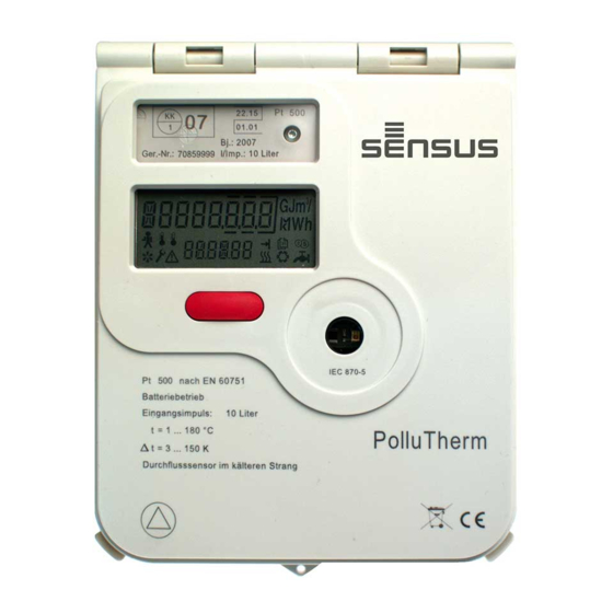
Heat / Cooling meter integrator PolluTherm
Installation and operation instructions
The integrator PolluTherm is used for energy
consumption measurement in heating or cooling
systems filled with the energy carrier liquid water.
PolluTherm may also be used with water
containing
antifreeze
correction factor. In this case the PolluTherm is
not officially metrologically calibrated. These
installation and operation instructions specify how
to install and operate the integrator PolluTherm.
They are an essential part of the supplied items
and shall be handed over to the final user.
Content
Supplied items ..................................................... 1
1. Technical data ................................................. 1
2. Safety instructions ........................................... 2
3. Required tools .................................................. 2
4. Combination of the sub-units ........................... 2
4.1 Programming the input pulse value ............ 2
5. Installation of the sub-units .............................. 3
5.1 Flow sensor ................................................ 3
5.3 Mounting of the integrator ........................... 4
6. Connection of the sub-units ............................. 4
6.1 Connection of the flow sensor .................... 5
7. Exchange of the integrator module .................. 5
8. Display options ................................................ 6
8.1 User menu (example) ................................. 6
8.2 Target day menu (example) ....................... 7
8.3 Archive menu (example)............................. 7
8.4. Service menu (example) ............................ 8
8.6 Parameter menu (example) ........................ 9
9. Functional test, sealing .................................. 10
10. Potential error situations .............................. 10
11. Data interface and options ........................... 10
11.1 Optical interface ..................................... 10
11.3 Remote reading plug-in unit ................... 11
....................................................................... 11
11.5 USB plug-in unit (for M-Bus slot) ............ 11
®
meter .............................................................. 11
option) ............................................................ 11
option) ............................................................ 12
supply unit ...................................................... 12
sensor cables ..................................................... 12
2004/22EC (MID) ............................................... 14
using
a
programmed
Supplied items
Integrator PolluTherm (incl. temperature
sensors and immersion sleeves, where
appropriate)
Sealing material (self-lock seals, sealing
wire), cable binders for strain relief
Fastening material (2 screws,
2 dowels, C-rail)
These installation and operating instructions
1. Technical data
Integrator
Temperature measuring
range
Temperature difference
∆ = 3 ... 150 K
range
Switch-off threshold
0,15 K
Better than (%):
Measuring accuracy
+ (0,5 + ∆
Updating time and
integration cycles resp.:
- Temperatures
2 sec
- Flow rate, power
4 sec
- Energy, volume
4 sec (16 sec *)
* in case of battery supply
Physical acc. to EN 61107
Optical data interface
Data record acc. to EN 13757-3
Pt 500
Suitable temperature
Connection in two- or four-wire
sensors
technology
Power supply
Battery for 6 years
(certification period of the
(optional: 11 years)
meter may be defined by
or mains supply 230 V AC or
national laws)
24 V AC
Electromagnetic
Class E 1
environment condition
Mechanical environment
Class M 2
condition
Protection class
IP 54
Ambient temperature
5 ... 55 °C
Storing temperature
-20 ... +65 °C
Relative air humidity
< 93 %
Size (H x B x T)
ca. 159 x 125 x 52 mm
in terms of wall mounting
0,25
Pulse input value
or
in l
1
Display of the
integrator with
00000,000 000000,00 0000000,0 00000000
decimal digits for
m³, MWh or GJ
Pulse value in case
of remote heat
0,001
quantity reading in
MWh or GJ
Pulse value in case
of remote volume
1
reading in l
M H 6111 INT PolluTherm, page 1
= 1 ... 180 °C
/ ∆)
min
2,5
25
250,
or
or
1.000 or
10
100
10.000
0,01
0,1
1
10
100
1.000
Advertisement
Table of Contents

Related Manuals for Xylem SENSUS PolluTherm Integrator


Summary of Contents for Xylem SENSUS PolluTherm Integrator
-
Page 1: Table Of Contents
Heat / Cooling meter integrator PolluTherm Installation and operation instructions The integrator PolluTherm is used for energy Supplied items consumption measurement in heating or cooling systems filled with the energy carrier liquid water. Integrator PolluTherm (incl. temperature PolluTherm may also be used with water sensors and immersion sleeves, where containing antifreeze... -
Page 2: Safety Instructions
Heat / Cooling meter integrator PolluTherm Installation and operational instructions 3. Required tools Appropriate spanner wrench or screw wrench 2. Safety instructions for screw connection and flange screws respectively. The installation of PolluTherm requires Slot screw driver 0,5 x 3 for clamp terminal adequate professional knowledge and should block be carried out by specially trained persons... -
Page 3: Installation Of The Sub-Units
Heat / Cooling meter integrator PolluTherm Installation and operation instructions 5. Installation of the sub-units PolluTherm can not only be used as a heat meter but also as a cooling meter (optional: PolluTherm H, PolluTherm X H, s. a. chapter 11.10). Therefore the text hereinafter includes following terms: Return pipe of heating systems: Colder line... -
Page 4: Mounting Of The Integrator
Heat / Cooling meter integrator PolluTherm Installation and operational instructions flush the pipe system thoroughly. Then close the shut-off valves, remove the fitting piece, clean the sealing surfaces and install the flow sensor using new gaskets. Take care to not reduce the pipe diameter by bad positioning of the gaskets, particularly if flanged versions are installed. -
Page 5: Connection Of The Flow Sensor
Heat / Cooling meter integrator PolluTherm Installation and operation instructions 6.1 Connection of the flow sensor The pulse cable is connected to terminal 10 (+) and 11 (-). Polarity can be disregarded for flow sensors with Reed contacts. An extension of the connection cable is only permitted with shielded cable. -
Page 6: Display Options
Heat / Cooling meter integrator PolluTherm Installation and operational instructions figure 12). Then pull the module carefully forwards. User menu Target day menu Archive menu Position of the fastening Service menu Control menu for tariff purposes Figure 12: Removal of the module fastening screw Parameter menu Multi-pole socket... -
Page 7: Target Day Menu (Example)
Heat / Cooling meter integrator PolluTherm Installation and operation instructions Target day value for Pulse value of the flow heat and cooling energy sensor resp. Tariff consumption 1 * Target day value for (if activated) volume Target day value for Tariff consumption cold * tariff 1 (if activated) -
Page 8: Service Menu (Example)
Heat / Cooling meter integrator PolluTherm Installation and operational instructions Absolute maximum Tariff consumption cold power incl. date (if activated) * (average) Absolute maximum Consumption first external power incl. time meter * (average) Absolute maximum Consumption second temperature in warmer external meter * line incl. -
Page 9: Control Menu For Tariff Purposes (Example)
Heat / Cooling meter integrator PolluTherm Installation and operation instructions At the beginning “000“ appears. Push the key for approx. 2 seconds; the zero on the left side starts Checksum flashing. By continuously pushing the key the value of the flashing digit can be changed. As soon as the desired value is obtained release the High-resolution energy key. -
Page 10: Functional Test, Sealing
Heat / Cooling meter integrator PolluTherm Installation and operational instructions In most cases the error situation „Err 1010“ is Reset absolute maxima * caused by temporary system conditions, where the temperature in the warmer line drops by at least 3K below the temperature in the colder line. Reset failure hours * In case of all other error codes please contact our Technical Service Centre. -
Page 11: Remote Reading Plug-In Unit
Heat / Cooling meter integrator PolluTherm Installation and operation instructions The factory presetting of the secondary address available as autonomous M-Bus meters on the M- and the customer number corresponds to the Bus. The consumption of the pulse meters will not serial number shown on the meter housing). -
Page 12: Optional Integrated Data Logger (Ordering Option)
Heat / Cooling meter integrator PolluTherm Installation and operational instructions For a detailed description please refer to At an automatic switch-over point this PolluTherm installation manual MH 1122. version switches over between metering heating and cooling energy. The switch-over point to cool metering is preset in the factory to: 12. - Page 13 Heat / Cooling meter integrator PolluTherm Installation and operation instructions By connecting the two additional wires for each temperature sensor at the terminal block of the integrator, i.e. for the higher temperature 1 and 2 and for the lower 3 and 4, the electric resistance of the extension cable or cables does/do not influence the measurement and the reading of the temperatures.
-
Page 14: Annex 1: Declaration Of Conformity Acc. Directive 2004/22Ec (Mid)
Heat / Cooling meter integrator PolluTherm Installation and operational instructions Annex 1: Declaration of conformity acc. directive 2004/22EC (MID) M H 6111 INT PolluTherm, page 14...
Need help?
Do you have a question about the SENSUS PolluTherm Integrator and is the answer not in the manual?
Questions and answers