Lantronix SISPM1040-384-LRT-C Install Manual
Managed hardened poe+ switches
Hide thumbs
Also See for SISPM1040-384-LRT-C:
- Quick start manual (2 pages) ,
- Web user manual (503 pages)

Related Manuals for Lantronix SISPM1040-384-LRT-C


Summary of Contents for Lantronix SISPM1040-384-LRT-C
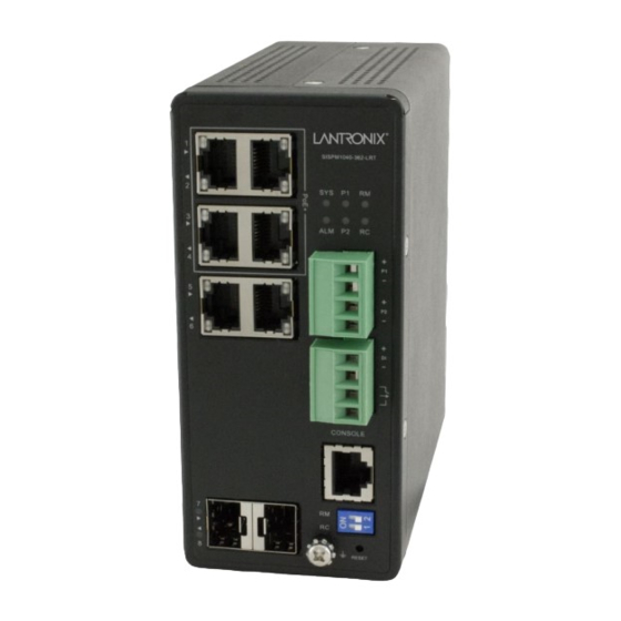
- Page 1 SISPM1040-384-LRT-C SISPM1040-362-LRT SISPM1040-384-LRT-C & SISPM1040-362-LRT Managed Hardened PoE+ Switches Install Guide Part Number 33727 Revision J September 2022...
- Page 2 Intellectual Property © 2022 Lantronix, Inc. All rights reserved. No part of the contents of this publication may be transmitted or reproduced in any form or by any means without the written permission of Lantronix. Lantronix is a registered trademark of Lantronix, Inc. in the United States and other countries.
-
Page 3: Safety Warnings And Cautions
Anyone using this product in such an application without express written consent of an officer of Lantronix does so at their own risk and agrees to fully indemnify Lantronix for any damages that may result from such use or sale. -
Page 4: Table Of Contents
Lantronix Install Guide, SISPM1040-362-LRT and SISPM1040-384-LRT-C Contents Safety Warnings and Cautions ......................3 Introduction ..........................6 Product Descriptions ........................6 Ordering Information ........................6 Manual Overview ........................7 Front Panel ..........................7 LED Descriptions ........................8 Front Panel 2-Position DIP Switch ................... 11 Rings Support ........................... - Page 5 Lantronix Install Guide, SISPM1040-362-LRT and SISPM1040-384-LRT-C IEEE 802.3bt Power Input Ripple and Noise Specification ..........30 Troubleshooting PoE Problems ....................30 Related Manuals ........................32 Device Label and Box Label ..................... 32 Record Device and System Information ................... 33 Features and Specifications ..................... 34 Key Features ..........................
-
Page 6: Introduction
It can supply up to 30 Watts per port on all four PoE ports simultaneously. The SISPM1040-362-LRT and SISPM1040-384-LRT-C differ mainly in port count as noted in this manual. These switches include embedded Device Management System (DMS) software that provides the advanced tools necessary for total management of all IP addressable devices. -
Page 7: Manual Overview
Lantronix Install Guide, SISPM1040-362-LRT and SISPM1040-384-LRT-C Lantronix offers a full line of small form factor pluggable (SFP) transceivers. For SFP Modules more information, see the Lantronix webpage. Sold separately. EDCA-DIO-01 Enclosure Door Contact Alarm. Sold separately. OCA-P181610 18x16x10” Polycarbonate Enclosure. Sold separately. -
Page 8: Led Descriptions
Lantronix Install Guide, SISPM1040-362-LRT and SISPM1040-384-LRT-C LED Descriptions The front panel LEDs provide switch status as follows: SYS (System) LED: indicates if the system is ready or not. P1 and P2 (Power LEDs): indicate whether the switch is powered up correctly. - Page 9 Lantronix Install Guide, SISPM1040-362-LRT and SISPM1040-384-LRT-C ALM (Alarm) LED The ALM (Alarm) LED lights if monitored temperature or internal voltages are exceeded. Issue critical stage for High / Low Voltage alarm (Power A or B Voltage) Lit Alarm LED in RED Color if Test-point (max) < Volts or if Test-point (min) < Volts.
- Page 10 Lantronix Install Guide, SISPM1040-362-LRT and SISPM1040-384-LRT-C Check the port status by reading the LED behaviors per the table below. Table 4: Port Status LEDs Color State Description The port is enabled and has established a link to the connected device, and Green the connection speed is 1000Mbps.
-
Page 11: Front Panel 2-Position Dip Switch
Lantronix Install Guide, SISPM1040-362-LRT and SISPM1040-384-LRT-C Table 5: RM (Ring Master) and RC (Rapid-Chain) LEDs RM (Ring Master) RC (Rapid-Chain) disable disable Green Ring Master is Enabled Rapid-Chain (Active path) Amber Ring Slave is Enabled Rapid-Chain (Backup path) Error: Rapid-Chain Switch did not find the... -
Page 12: Rings Support
Note that Spanning Tree must be disabled for Rapid Ring operation. EPS and ERPS are standard protocols that can be used between various vendor switches. Rapid Rings protocols are only for Lantronix switches that support Rapid Ring protocols. Notes: 1. The DIP Switches are only for Single Ring and Ring Failover. -
Page 13: Reset Button
Lantronix Install Guide, SISPM1040-362-LRT and SISPM1040-384-LRT-C RESET Button By pressing the RESET button for a specific amount of time, you can: Reset the Switch: to reboot and get the switch back to the previous configuration settings saved. Restore the Switch to Factory Defaults: to restore the original factory default settings back to the switch. -
Page 14: Installing The Switch
Lantronix Install Guide, SISPM1040-362-LRT and SISPM1040-384-LRT-C Installing the Switch Package Contents Verify that you have received the items below. Contact your sales representative if any item is missing. Please save the packaging for possible future use. • One Switch •... -
Page 15: Din Rail Mounting
Lantronix Install Guide, SISPM1040-362-LRT and SISPM1040-384-LRT-C DIN Rail Mounting 1. Attach the DIN Rail mounting kit to chassis back panel. Insert screws and tighten with a screwdriver. Figure 2: Attaching DIN Rail Kit to the Switch 2. Insert the upper lip of the DIN rail into the DIN-rail mounting kit. Press the switch towards the DIN rail until it snaps into place. -
Page 16: Wall Mounting (Optional)
Lantronix Install Guide, SISPM1040-362-LRT and SISPM1040-384-LRT-C Wall Mounting (Optional) See the WMBH-01 manual for more details. 1. Attach the wall mounting plates to rear panel of the chassis. Insert screws and tighten then with a screwdriver to secure the plates. -
Page 17: Connecting Copper Ports
48~56V range to prevent damage to PDs. Installing SFP Modules On the SISPM1040-384-LRT-C, you can install or remove an SFP module from a SFP port without having to power off the switch. Note: Use UL Listed Transceiver SFPs rated 3.3Vdc, Laser Class 1. See the SFP manual for cautions and warnings. -
Page 18: Connecting The Di/Do Relay Wires
Lantronix Install Guide, SISPM1040-362-LRT and SISPM1040-384-LRT-C Connecting the DI/DO Relay Wires The lower Euro Block (Terminal Block) provides connection of the optional DI/DO Relay wires. Figure 9: Connecting DI/DO Relay Wires 1. Insert the negative (ground)/positive DI/DO Relay wires into the terminals, respectively. -
Page 19: Digital Input And Digital Output Use Case
Lantronix Install Guide, SISPM1040-362-LRT and SISPM1040-384-LRT-C Digital Input and Digital Output Use Case The switch supports Digital Input and Digital Output. The Digital Input enables the switch to detect and log external device status (such as door intrusion detector). The Digital Output could be used to tell administrators if the switch port shows link down, link up or power failure. -
Page 20: Connecting To Dc Power
Lantronix Install Guide, SISPM1040-362-LRT and SISPM1040-384-LRT-C An external alarm device (e.g., power supply or IP camera) can activate this input pin. Level 0 (Low): 0V to 6V Level 1 (High): 10V to 24V For DO, it’s similar but the switch is the alarm device, when the switch has temperature or voltage alarm, it will trigger the digital output (24V/1A) to the external device such as a contact relay. -
Page 21: Power Connection
Lantronix Install Guide, SISPM1040-362-LRT and SISPM1040-384-LRT-C Power Connection ATTENTION: This case must be earth grounded. No DC input may be earth grounded. Use Isolated Power Supply. Negative DC voltage is not supported. Recommended Best Practice: First, connect the power supply to the switch while powered off. -
Page 22: Initial Switch Configuration
Lantronix Install Guide, SISPM1040-362-LRT and SISPM1040-384-LRT-C Initial Switch Configuration Initial Switch Configuration via Web Browser After powering up the switch for the first time, you can perform the initial switch configuration using a web browser. For managing other switch features, refer to the Web User Guide. -
Page 23: Connect The Switch To A Windows 10 Pc
Lantronix Install Guide, SISPM1040-362-LRT and SISPM1040-384-LRT-C Connect the PC to any port on the switch using a standard Ethernet cable, and check the port LED on the switch to make sure the link status of the PC’s is OK. Run your Web browser on the PC, and enter the factory default IP address, to access the switch’s Web interface. -
Page 24: Initial Switch Configuration Via Cli
Lantronix Install Guide, SISPM1040-362-LRT and SISPM1040-384-LRT-C Initial Switch Configuration via CLI Use an RJ-45 cable to connect a terminal or PC/terminal emulator to the switch port to access the CLI. Attach the RJ-45 serial port on the switch front panel to the cable for Telnet/CLI configuration. -
Page 25: Troubleshooting
Lantronix Install Guide, SISPM1040-362-LRT and SISPM1040-384-LRT-C Troubleshooting Basic Troubleshooting The switch front panel LEDs provide troubleshooting information. You can also get statistics from the Web UI, the CLI, or from an SNMP workstation. Make sure your switch model supports the feature or function attempted; see chapter... -
Page 26: Troubleshooting Led Indications
Lantronix Install Guide, SISPM1040-362-LRT and SISPM1040-384-LRT-C Troubleshooting LED Indications The following table provides information to troubleshoot problems by taking actions based on the symptom. Symptom Possible Cause Suggested Solutions 1. Check if correct power cord is connected firmly to the switch and to the DC outlet socket. -
Page 27: Led Summary
Lantronix Install Guide, SISPM1040-362-LRT and SISPM1040-384-LRT-C LED Summary Category Color Function System status LED: LED Off: All Power is off. Global Green Green Lit: Switch FW Boot up is Ready. Green blinking: System is booting. Power 1 LED: Global Green LED Off: Power 1 off. -
Page 28: Poe Modes And Compliance
Lantronix Install Guide, SISPM1040-362-LRT and SISPM1040-384-LRT-C PoE Modes and Compliance PoE Deployment Environments A and B IEEE802.3at-2009 defines two deployment environments in section 33.4.1: Environment A: when both PSE and PD are located indoors, inside the same building. In this environment, there has to be electrical isolation between the PoE circuitry and the data circuitry inside a PSE. - Page 29 2. PoE cables are intended for intrabuilding use only. Connecting your Lantronix switch directly to PoE cables that run outside the building in which the switch is housed will void the user's warranty and could create a fire or shock hazard.
-
Page 30: Ieee 802.3Bt Power Input Ripple And Noise Specification
Lantronix Install Guide, SISPM1040-362-LRT and SISPM1040-384-LRT-C Legacy PD Detection / Capacitor Detection Legacy PDs refers to powered devices manufactured before the IEEE standard was finalized and do not have the expected PD signature required by the PSE's detection signal. Such PDs usually feature large capacitance as the detection signature that does not completely comply with the 802.3af specs. - Page 31 (unplug the switch, wait at least three seconds, then plug it back in. This will ensure a total system reset that should restore normal operation. Check if related features (LLDP mode, CDP mode) are enabled. See the Lantronix PoE Brochure for more information.
-
Page 32: Related Manuals
For Lantronix Documentation, Firmware, App Notes, etc. go to https://www.lantronix.com/technical-support/ Note that this manual provides links to third party web sites for which Lantronix is not responsible. Device Label and Box Label In addition to the device CLI and Web GUI, you can find device information on the device Serial Label and box Serial Label as shown below. -
Page 33: Record Device And System Information
Describe any action(s) already taken to resolve the problem (e.g., changing mode, rebooting, etc.): ________________ ________________________________________________________________________________________________________________________ ________________________________________________________________________________________________________________________ ________________________________________________________________________________________________________________________ The serial and revision numbers of all involved Lantronix products in the network: ________________________________ ________________________________________________________________________________________________________________________ ________________________________________________________________________________________________________________________ Describe your network environment (layout, cable type, etc.): ________________________________________________________... -
Page 34: Features And Specifications
SISPM1040-362-LRT: Managed Hardened PoE+ Switch; provides (4) 10/100/1000Base-T PoE+ ports + (2) 10/100/1000Base-T ports + (2) 100/1000Base-X SFP slots and one RJ45 Console port. SISPM1040-384-LRT-C: Managed Hardened PoE+ Switch; provides (8) 10/100/1000Base-T PoE+ RJ45 ports + (4) 100/1000Base-X SFP slots and one RJ45 Console port. - Page 35 Lantronix Install Guide, SISPM1040-362-LRT and SISPM1040-384-LRT-C Feature SISPM1040-362-LRT SISPM1040-384-LRT-C Hardware Performance Forwarding Capacity (Mpps) 11.904 17.586 Switching Capacity (Gbps) Mac Table (K) Jumbo Frames (Bytes) 9216 9216 SISPM1040-362-LRT Environmental Range SISPM1040-384-LRT-C -40 to 167F -40 to 167F Operating Temperature -40 to 75C...
-
Page 36: Software Features
Lantronix Install Guide, SISPM1040-362-LRT and SISPM1040-384-LRT-C Software Features SISPM1040-384-LRT-C and SISPM1040-362-LRT Ring Management Rapid Ring Enables self-recover time in less than 20ms. ITU-T G.8031 Supports ITU-T G.8031 Ethernet Linear Protection Switching (EPS). ITU-T G.8032 Supports ITU-T G.8032 Ethernet Ring Protection Switching (ERPS). - Page 37 Lantronix Install Guide, SISPM1040-362-LRT and SISPM1040-384-LRT-C SISPM1040-384-LRT-C and SISPM1040-362-LRT Used to support a Layer 2 multicast domain of snooping switches in the absence of a IGMP Querier multicast router. IGMP snooping with proxy reporting or report suppression actively filters IGMP IGMP Proxy packets in order to reduce load on the multicast router.
- Page 38 Lantronix Install Guide, SISPM1040-362-LRT and SISPM1040-384-LRT-C Quality of Service Hardware Queue Supports 8 hardware queues Strict priority and weighted round-robin (WRR). Scheduling Queue assignment based on DSCP and class of service. Port based. 802.1p VLAN priority based. Classification IPv4/IPv6 precedence / DSCP based.
-
Page 39: Mtbf Specifications
• Perform on-demand backup and restore of device configuration ConsoleFlow • Perform secure remote device firmware upgrades • Lantronix-hosted public cloud offering Lantronix Provisioning Manager allows easy administration of Lantronix devices. LPM lets you quickly update firmware, update configuration, and provision one or more devices simultaneously. MTBF Specifications MTBF Environment: GB, GC –... -
Page 40: Shared Features
Lantronix Install Guide, SISPM1040-362-LRT and SISPM1040-384-LRT-C Shared Features Primary Power Supply - DC Input Voltage Voltage and Frequency SISPM1040-384-LRT-C and SISPM1040-362-LRT 54 VDC dual inputs DC Nominal 48 to 57 VDC DC Operating Range Requires >48 VDC for PoE IEEE 802.3af (Max. 15.4W output) Requires >54 VDC for PoE+ IEEE 802.3at (Max. -
Page 41: Cable Specifications
Lantronix Install Guide, SISPM1040-362-LRT and SISPM1040-384-LRT-C Cable Specifications You may use unshielded twisted-pair (UTP) for RJ-45 connections: Category 3 or better for 10 Mbps connections, □ Category 5 or better for 100 Mbps connections, or □ Category 5, 5e, or 6 for 1000 Mbps connections. -
Page 42: Industrial Power Supply 25105
Lantronix Install Guide, SISPM1040-362-LRT and SISPM1040-384-LRT-C Industrial Power Supply 25105 Note: Both the switch and Power Supply 25105 must have their ground terminals connected to earth ground. Output Output Voltage 48VDC Current Rating 2.5A Power Rating 120 Watts Ripple & Noise Max... -
Page 43: Industrial Power Supply 25104
Lantronix Install Guide, SISPM1040-362-LRT and SISPM1040-384-LRT-C Industrial Power Supply 25104 Note: Both the switch and Power Supply 25104 must have their ground terminals connected to earth ground. Output Output Voltage 48VDC Current Rating Power Rating 240 Watts Ripple & Noise Max... -
Page 44: Power Supply Built-In Dc Ok Relay Contact
Lantronix Install Guide, SISPM1040-362-LRT and SISPM1040-384-LRT-C Terminal Torque: 7 Lb-in (DC connections at top of PS).Terminal Torque: 4.4 Lb-in (AC connections at bottom of PS). +V ADJ: access to small Phillips screw; turn clockwise to increase voltage. Adjustable, 48-55V. DC OK LED: lights to indicate a DC OK condition. -
Page 45: Power Supply Dimensions - 25104 (Sdr-240-48)
Lantronix Install Guide, SISPM1040-362-LRT and SISPM1040-384-LRT-C Power Supply Dimensions - 25104 (SDR-240-48) Dimensions (in mm) - 25104 (SDR-240-48) 33727 Rev. J https://www.lantronix.com/ Page 45 of 51... -
Page 46: Ps-Dc-Dual-5624T
Lantronix Install Guide, SISPM1040-362-LRT and SISPM1040-384-LRT-C PS-DC-DUAL-5624T Hardened 345 Watt Isolated PS with 56VDC and 24VDC Dual Output. The Power Supply provides 345W at 56VDC and is targeted for PoE applications. The Power Supply is fully compliant with IEEE 802.3af, at, and bt PoE standards for isolation. It provides a secondary fully-isolated 24V at 1.25A (30W) output for other... -
Page 47: Regulatory And Safety Information
Manufacture’s Name: Lantronix, Inc. Manufacture’s Address: 48 Discovery, Suite 250, Irvine, California 92618 Declares that the products: SISPM1040-362-LRT and SISPM1040-384-LRT-C Conform to the following Product Regulations: EN 55032: 2015:+AC: 2016 (Class A); CISPR 32: 2015+COR1: 2016 (Class A); EN 61000-3-2: 2014; EN 61000-3-3: 2013;... -
Page 48: High Risk Activities Disclaimer
Nuclear Facilities, Aircraft Navigation or Aircraft Communication Systems, Air Traffic Control, Life Support, or Weapons Systems ("High Risk Activities"). Lantronix and its supplier(s) specifically disclaim any expressed or implied warranty of fitness for such High Risk Activities. -
Page 49: Electrical Safety Warnings
Lantronix Install Guide, SISPM1040-362-LRT and SISPM1040-384-LRT-C Warning: This case must be earth grounded. No DC input may be earth grounded. Use Isolated Power Supply. Warning: Turn the external power source OFF and ensure that the power module is disconnected from the external power source before performing any maintenance. -
Page 50: Class I Division 2
Lantronix Install Guide, SISPM1040-362-LRT and SISPM1040-384-LRT-C Class I Division 2 The product has been evaluated to the requirements of UL and the Canadian National Standard: USL – ANSI/ISA 12.12.01-2015, Nonincendive Electrical Equipment for Use in Class I and II, Division 2 and Class III, Divisions 1 and 2 Hazardous (Classified) Locations, Approved 21 August 2015. - Page 51 Toll Free: 800-526-8766 Phone: 949-453-3990 Fax: 949-453-3995 Technical Support Online: https://www.lantronix.com/technical-support/ Sales Offices For a current list of our domestic and international sales offices, go to the Lantronix web site at www.lantronix.com/about/contact. 33727 Rev. J https://www.lantronix.com/ Page 51 of 51...
Need help?
Do you have a question about the SISPM1040-384-LRT-C and is the answer not in the manual?
Questions and answers