Advertisement
SISPM1040-3xxx-L
Quick Start Guide
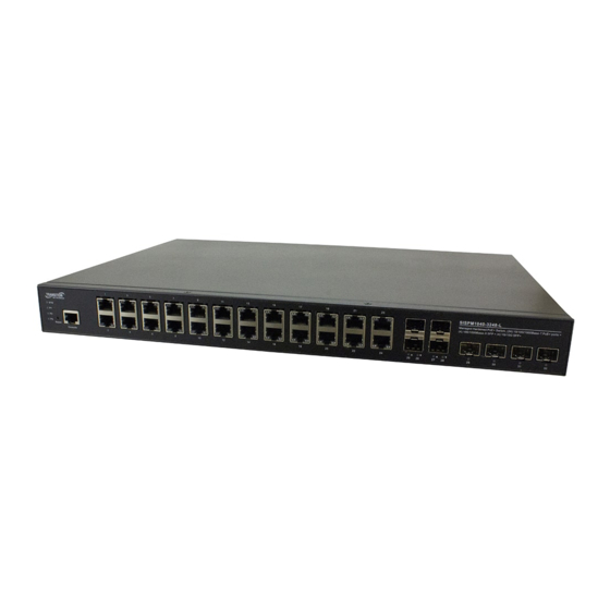
The SISPM1040-3248-L is a managed Hardened PoE+ Switch provides
(24) 10/100/1000 PoE+ ports, 4 100/1000 dual speeds SFP ports with
additional (4) 1G/10G SFP+ slot, it supplies up to 370W PoE budget over
24 PoE+ ports.
The SISPM1040-3166-L is a managed Hardened PoE+ Switch provides (16) 10/100/1000 PoE+ ports, 4 100/1000 dual
speeds SFP ports with additional (2) 1G/10G SFP+ slot, it supplies up to 250W PoE budget over 16 PoE+ ports.
See the SISPM1040-3xxx-L Install Guide for important Safety Warnings & Cautions, Features, Specs, Software features,
Front panel, LEDs, Mounting, Connecting, Installing, Power Supply, Initial config, and Troubleshooting information.
LED
Descriptions: The front panel LEDs display switch status. The three types of LEDs are:
System LED: Indicates if the switch is powered up correctly or if there is a system alarm triggered.
Power LEDs (P1/P1: DC LED, P3: AC LED): Indicate if the switch is powered up correctly.
Port Status LEDs: Indicate the current status of each port.
Reset
Button: Press to toggle the LEDs to display Link/Activity/Speed or just display PoE port status. By pressing the
Reset button for a certain period, you can 1. Reset the switch (reboot and get the switch back to the previously saved
configuration settings). 2. Restore the switch to Factory Defaults. See the Install Guide.
Back
Panel: provides 52-57 VDC and 100-250 VAC power inputs and DI/DO relay. See the Install Guide for DI/DO
configuration information.
Package Contents
: Make sure you have received one Switch with one Power Supply installed, one DB-9 to RJ45 Cable,
AC Power cord (Option), four rubber feet, this manual, Rack Mount Brackets, and a secondary Power Supply (Option).
19-inch Rack
Mounting: 1. Attach the mounting brackets to both sides of the chassis. Insert screws and tighten with a
screwdriver to secure the brackets. 2. Place the switch on a rack shelf in the rack and push it in until the oval holes in the
brackets align with the mounting holes in the rack posts. 3. Attach the brackets to the posts; insert screws and tighten.
Desk or Shelf
Mounting: 1. Verify that the workbench is sturdy and reliably grounded. 2. Attach the four adhesive
rubber feet to the bottom of the switch.
Installing SFP
Modules: You can install or remove a Hardened SFP/SFP+ Module from an SFP port without powering off
the switch. Note: The SFP ports should use UL Listed Optional Transceiver product, Rated 3.3Vdc, Laser Class 1.
1. Make sure the SFP is oriented correctly. 2. Insert the module into the SFP port. 3. Press firmly to ensure that the
module seats into the connector.
ATTENTION:
This case must be earth grounded. No DC input may be earth grounded.
Use Isolated Power Supply.
Caution:
The switch is an indoor device. If it used with outdoor devices such as outdoor IP cameras, you are strongly
suggested to install a surge protector or surge suppressor to protect the switch. See the Install Guide.
Power
Supplies: 25104 Input: 85-264 VAC, 124-370 VDC; Output: 48 ~ 55 VDC, 5A, 240 Watts. 25160 Input 90-264 VAC,
127-370 VDC; Output: 48 ~ 55 VDC, 10A, 480 Watts. PS-DC-DUAL-5624T Power Supply with 56VDC and 24VDC Dual
Output. See the Install Guide.
connect the power supply to power. Otherwise catastrophic product failure may occur. 1. Verify that power is off to the
DC circuit that you are going to attach to the switch PoE DC-input connector. This can be either of the two power
supplies (AC-input or DC-input) or site source DC. 2. As an added precaution, place an appropriate safety flag and
lockout device at the source power circuit breaker, or place a piece of adhesive tape over the circuit breaker handle to
prevent accidental power restoration while you are working on the circuit.
from the switch after a successfully boot: 1. Turn off power to the switch. 2. Disconnect the cables.
33761 Rev. D
WARNING:
Hot Surface Do Not Touch.
Power
Connection: Warning:
https://www.lantronix.com/
SISPM1040-3xxx-L Quick Start Guide
Connect the power supply to the switch first, and then
Power
Disconnection: To disconnect power
Page 1 of 2
Advertisement
Table of Contents

Related Manuals for Lantronix SISPM1040-3 L Series


Summary of Contents for Lantronix SISPM1040-3 L Series
- Page 1 Power Disconnection: To disconnect power from the switch after a successfully boot: 1. Turn off power to the switch. 2. Disconnect the cables. 33761 Rev. D https://www.lantronix.com/ Page 1 of 2...
- Page 2 Technical Support: http://www.transition.com/support. Sales Offices: www.lantronix.com/about/contact. © 2021 Lantronix, Inc. All rights reserved. No part of the contents of this publication may be transmitted or reproduced in any form or by any means without the written permission of Lantronix. Lantronix is a registered trademark of Lantronix, Inc. in the United States and other countries.
Need help?
Do you have a question about the SISPM1040-3 L Series and is the answer not in the manual?
Questions and answers