
Subscribe to Our Youtube Channel
Related Manuals for Lantronix SISPM1040 L3 Series


Summary of Contents for Lantronix SISPM1040 L3 Series
- Page 1 SISPM1040-xxxx-L3 Layer 3 Managed Hardened PoE + Switch family SISPM1040-2248-L3, SISPM1040-3248-L3, and SISPM1040-3166-L3 Install Guide Part Number 33855 Revision A June 2022...
- Page 2 SISPM1040-xxxx-L3 Install Guide Intellectual Property © 2022 Lantronix, Inc. All rights reserved. No part of the contents of this publication may be transmitted or reproduced in any form or by any means without the written permission of Lantronix. Lantronix is a registered trademark of Lantronix, Inc. in the United States and other countries.
-
Page 3: Table Of Contents
Lantronix SISPM1040-xxxx-L3 Install Guide Contents Product Description ..............................5 Ordering Information ..............................5 About This Manual ..............................5 Related Manuals ...............................6 Features ..................................6 Specifications ................................7 Application Example ..............................8 Pre-Installation ................................9 Safety ..................................9 Unpacking ................................9 Package Contents ..............................9 Front Panels ................................10 LED Descriptions ..............................11 Reset Button ................................ - Page 4 Lantronix SISPM1040-xxxx-L3 Install Guide LED Troubleshooting ............................31 Compliance and Safety Information ........................33 Declaration of Conformity ............................ 33 FCC Regulations ..............................33 High Risk Activities Disclaimer ..........................34 Cautions and Warnings ............................34 Electrical Safety Warnings ........................... 35 33855 Rev. A...
-
Page 5: Product Description
SISPM1040-xxxx-L3 Install Guide Product Description The Lantronix SISPM1040-xxxx-L3 are next generation Industrial L3+ managed GbE switches. They are affordable managed switches that provide a reliable infrastructure for your business network. These switches deliver the intelligent features you need to improve the availability of your critical business applications, protect your sensitive information, and optimize your network bandwidth to deliver information and applications more effectively. -
Page 6: Related Manuals
A printed Quick Start Guide is shipped with each SISPM1040-xxxx-L3 switch. For the latest information, see the online manual. Note that this manual provides links to third party web sites for which Lantronix is not responsible. Related manuals include: 1. Product Support Postcard, 33504 2. -
Page 7: Specifications
Lantronix SISPM1040-xxxx-L3 Install Guide Specifications IEEE 802.3, IEEE 802.3u, IEEE 802.3z, IEEE 802.3ae, IEEE 802.3x, IEEE 802.3ad, IEEE 802.1D, IEEE 802.1w, IEEE 802.1s, IEEE 802.1Q, IEEE 802.1p, IEEE 802.1ad, IEEE 802.1AB, IEEE 802.3af, IEEE 802.3at, IEEE / Network Standards IEEE 802.3az, IEEE 802.3ah, IEEE 802.1ag, IEC 62439-2, IEEE 802.1X, IEEE 802.1v, IEEE 1588v2 PTP... -
Page 8: Application Example
Lantronix SISPM1040-xxxx-L3 Install Guide Application Example High-resolution IP camera, IP PTZ camera High-performance wireless access points Intelligent Transportation System (ITS) Oil and gas field sites Where routing between VLANs is needed where different areas (e.g., intersections) or types of data (video, ... -
Page 9: Pre-Installation
Lantronix SISPM1040-xxxx-L3 Install Guide Pre-Installation Safety Electrical Safety Warnings on page for safety information in multiple languages. • Do not use this product near water, for example, in a wet basement or near a swimming pool. • Avoid using this product during an electrical storm. There may be a remote risk of electric shock from lightning. -
Page 10: Front Panels
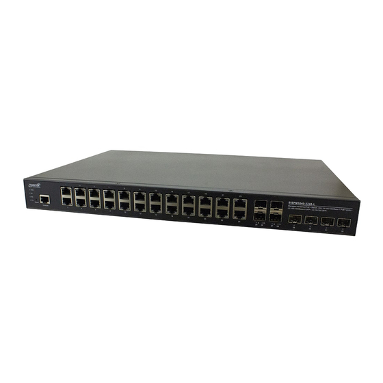
Lantronix SISPM1040-xxxx-L3 Install Guide Front Panels The switch front panel provides the LEDs, ports, and Reset button as shown and described below. SISPM1040-2248-L3 SISPM1040-3248-L3 SISPM1040-3166-L3 33855 Rev. A https://www.lantronix.com/... -
Page 11: Led Descriptions
Lantronix SISPM1040-xxxx-L3 Install Guide LED Descriptions The front panel LEDs provide switch status checking and monitoring. There are three types of LEDs as follows: System LED: Indicates if the switch is powered up correctly or not, or, indicates if there is a system alarm triggered for troubleshooting. - Page 12 Lantronix SISPM1040-xxxx-L3 Install Guide Green The port is enabled and supplying power to connected device. Amber An abnormal state, such as overload status, was detected in the switch. RJ45 Ports Right Side The port has no active network cable connected, or it is not connected a PoE PD device.
-
Page 13: Reset Button
Lantronix SISPM1040-xxxx-L3 Install Guide Reset Button By pressing the Reset button for certain period of time, you can perform these tasks: Reset the switch: To reboot and get the switch back to the previous configuration settings saved. Restore the switch to Factory Defaults: To restore the switch back to its original factory default settings. -
Page 14: Device And Box Labels
Lantronix SISPM1040-xxxx-L3 Install Guide Device and Box Labels The device and box labels provide information to help identify your switch to the Tech Support Specialist. Installing the Switch Note: the unit is to be connected only to networks without routing to the outside plant. -
Page 15: Grounding
Lantronix SISPM1040-xxxx-L3 Install Guide Grounding The switch has a grounding screw provided for grounding. Equipment grounding is vital to ensure safe operation. The installer must ensure that the switch is properly grounded during and after installation. After the Switch is mounted and connected, the front panel grounding screw can be used for grounding. -
Page 16: Mounting The Switch In A 19-Inch Rack
Lantronix SISPM1040-xxxx-L3 Install Guide Mounting the Switch in a 19-inch Rack 1. Attach the mounting brackets to both sides of the chassis. Insert screws and tighten then with a screwdriver to secure the brackets. Attaching Brackets to the Switch 2. Place the switch on a rack shelf in the rack. Push it in until the oval holes in the brackets align with the mounting holes in the rack posts. -
Page 17: Installing Sfp/Sfp+ Modules
Lantronix SISPM1040-xxxx-L3 Install Guide Installing SFP/SFP+ Modules You can install or remove a mini-GBIC SFP/SFP+ module from an SFP/SFP+ port without having to power off the switch. Note: The SFP/SFP+ ports should use UL Listed Optional Transceiver product, Rated 3.3Vdc, Laser Class 1. -
Page 18: Connecting Powered Devices (Pds)
Lantronix SISPM1040-xxxx-L3 Install Guide Connecting Powered Devices (PDs) Note that this device does not comply with IEEE 802.3at at 48‐51.4 VDC, or with IEE 802.3bt at 48‐53.4 VDC. This device drops ~1.3V from Vin to PSEout. IEEE requires these PSEout voltages at the PSE output into the cable: •... -
Page 19: Connect The Dc Power Wires
Lantronix SISPM1040-xxxx-L3 Install Guide Connect the DC Power Wires Warning: Connect the power supply to the switch first, and then connect the power supply to power. Otherwise, catastrophic product failure may occur. 1. Place an appropriate safety flag and lockout device at the source power circuit breaker or place a piece of adhesive tape over the circuit breaker handle to prevent accidental power restoration while you are working on the circuit. -
Page 20: Connecting The Di/Do Relay Wires
Lantronix SISPM1040-xxxx-L3 Install Guide Connecting the DI/DO Relay Wires 1. Insert the negative (ground)/positive DI/DO Relay wires into the +/- terminals, respectively. 2. To keep the DI/DO Relay wires from pulling loose, use a small flat-blade screwdriver to tighten the wire- clamp screws on the front of the terminal block connector. -
Page 21: Digital Input And Digital Output Use Case
Lantronix SISPM1040-xxxx-L3 Install Guide Digital Input and Digital Output Use Case The switch supports Digital Input and Digital Output. The Digital Input enables the switch to detect and log external device status (such as door intrusion detector). The Digital Output could be used to tell administrators if the switch port shows link down, link up or power failure. -
Page 22: Power Supply Information
Lantronix SISPM1040-xxxx-L3 Install Guide Power Supply Information Power supply options include the 25160 and PS-DC-DUAL-5624T as shown and described below. Note: When both AC and DC power inputs are connected, the DC input will supply power since the DC input is higher voltage than the AC input. -
Page 23: Power Supply Views (25160)
Lantronix SISPM1040-xxxx-L3 Install Guide Certifications • Safety: UL508, TUV EN62368-1; IEC60068-2-6 (Vibration) • EMC Emission: EN55011, EN5032(CISPR32), EN61204-3 Class B, EN61000-3-2, EN61000-3-3; • EMC Immunity: EN61000-4-2, EN61000-4-3, EN61000-4-4, EN61000-4-5, EN61000-4-6, EN61000-4-8, EN61000-4-11, EN55024, EN61000-6-2, EN50082-2, EN61204-3, SEMI F47, GL Approved... -
Page 24: Power Supply Dimensions (25160)
Lantronix SISPM1040-xxxx-L3 Install Guide Power Supply Dimensions (25160) Width: 85.5 mm (3.36 in.) Height: 125.2 mm (4.92 in.) Depth: 128.5 mm (5.05 in.) ADMISSIBLE DIN-RAIL: TS35/7.5 OR TS35/15 33855 Rev. A https://www.lantronix.com/... -
Page 25: Power Supply Pin Descriptions (25160)
Lantronix SISPM1040-xxxx-L3 Install Guide Power Supply Pin Descriptions (25160) Terminal Pin No. Assignment (TB1) Pin No. Assignment AC/N AC/L Terminal Pin No. Assignment (TB2) Pin No. Assignment DC OUTPUT +V DC OUTPUT -V Relay Contact DC OK Relay Contact Contact Close PSU turns on / DC OK. -
Page 26: Ps-Dc-Dual-5624T 340W Standalone Power Supply
PS-DC-DUAL-5624T 340W Standalone Power Supply Lantronix PS-DC-DUAL-5624T Standalone Power Supplies are designed to provide power to the Lantronix SISPM1040-xxxx-L3 switch. This standalone power supply can be installed in a 19” Rack with 1RU high. The Power Supply provides 340W at 56VDC and is targeted for PoE applications. -
Page 27: Initial Switch Configuration
Lantronix SISPM1040-xxxx-L3 Install Guide Initial Switch Configuration Initial Switch Configuration via Web Browser After powering up the switch for the first time, you can perform the initial switch configuration using a web browser. For managing other switch features, refer to the Web User Guide for details. -
Page 28: Initial Switch Configuration Via Cli
Lantronix SISPM1040-xxxx-L3 Install Guide Initial Switch Configuration via CLI 1. Use an RJ‐45 cable to connect a terminal or PC/terminal emulator to the switch port to access the CLI. 2. Attach the RJ‐45 serial port on the switch front panel to the cable for Telnet/CLI configuration. -
Page 29: Troubleshooting
Lantronix SISPM1040-xxxx-L3 Install Guide Troubleshooting Basic Troubleshooting 1. Make sure your switch model supports the feature or function attempted; see Features on page and check the Release Notes for your particular firmware version. 2. Verify the install process; see Installing the Switch on page 14. -
Page 30: Troubleshooting Table
Lantronix SISPM1040-xxxx-L3 Install Guide Troubleshooting Table The following table provides information for users to easily troubleshoot problems by taking actions based on the suggested solutions within. Symptom Possible Cause Suggested Solutions 1. Check if correct power cord is connected firmly to the switch and to the AC/DC outlet socket. -
Page 31: Led Troubleshooting
Lantronix SISPM1040-xxxx-L3 Install Guide LED Troubleshooting Color State Description The port is enabled and established a link to connected device, and the Green connection speed is 1000Mbps. The port is transmitting/receiving packets, and the connection speed is Green Blinking 1000Mbps. - Page 32 Lantronix SISPM1040-xxxx-L3 Install Guide Color State Description The port is enabled and established a link to connected device, and the Green connection speed is 1Gbps. The port is transmitting/receiving packets, and the connection speed is Green Blinking 1Gbps. The port has no active network cable connected, or it is not established a link to connected device.
-
Page 33: Compliance And Safety Information
Lantronix SISPM1040-xxxx-L3 Install Guide Compliance and Safety Information Declaration of Conformity Manufacture’s Name: Lantronix, Inc. Manufacture’s Address: 7535 Irvine Center Drive, Suite100, Irvine, CA 92618, USA Declares that the products: SISPM1040-3166-L3, SISPM1040-2248-L3, and SISPM1040-3248-L3 Conform to the following Product Regulations: Emission: EN 55032: 2015+A11:2020, CISPR 32: 2015+COR1:2016, EN IEC 61000-3-2:2019, EN 6100-3-3: 2013+A1: 2019, AS/NZS CISPR 32: 2015. -
Page 34: High Risk Activities Disclaimer
Lantronix SISPM1040-xxxx-L3 Install Guide High Risk Activities Disclaimer Components, units, or third-party products used in the product described herein are NOT fault-tolerant and are NOT designed, manufactured, or intended for use as on-line control equipment in the following hazardous environments requiring fail-safe controls: the operation of Nuclear Facilities, Aircraft Navigation or Aircraft Communication Systems, Air Traffic Control, Life Support, or Weapons Systems ("High Risk Activities"). -
Page 35: Electrical Safety Warnings
Lantronix SISPM1040-xxxx-L3 Install Guide Electrical Safety Warnings Electrical Safety IMPORTANT: This equipment must be installed in accordance with safety precautions. Elektrische Sicherheit WICHTIG: Für die Installation dieses Gerätes ist die Einhaltung von Sicherheitsvorkehrungen erforderlich. Elektrisk sikkerhed VIGTIGT: Dette udstyr skal installeres i overensstemmelse med sikkerhedsadvarslerne. - Page 36 Irvine, CA 92618, USA Toll Free: 800-526-8766 Phone: 949-453-3990 Fax: 949-453-3995 Technical Support Online: https://www.lantronix.com/technical-support/ Sales Offices For a current list of our domestic and international sales offices, go to the Lantronix web site at www.lantronix.com/about/contact. 33855 Rev. A https://www.lantronix.com/...
Need help?
Do you have a question about the SISPM1040 L3 Series and is the answer not in the manual?
Questions and answers