Advertisement
Quick Links
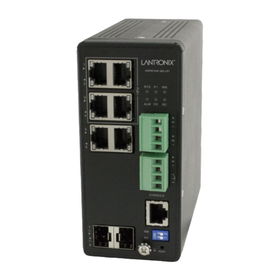
SISPM1040-384-LRT-C & SISPM1040-362-LRT
Hardened Managed PoE+ Switches
Quick Start Guide
The SISPM1040-384-LRT-C and SISPM1040-362-LRT are industrial L2+ managed GbE
switches. See the Install Guide for important
Specs, Options, Installation, etc.
Package Contents
Verify you have received 1 Switch, 1 Terminal Block, 1 printed Quick Start Guide, 1 DIN Rail mounting bracket and 2
screws, a DB-9 to RJ-45 Console Cable, and Power Supply (one or two; optional).
Mount the Switch
See the Install Guide to mount the switch on a DIN Rail, wall, or desktop.
Connect RJ-45 Ports
1. Connect the provided DB-9 to RJ-45 Console Cable to a PC or Terminal and to the CONSOLE port on the switch.
2. Connect the Ethernet RJ45 Ports to the CAT3-CAT6 Ethernet cables/far end devices. Only connect PDs which support
power input in 48~56V range to prevent damage to PDs. See the Install Guide for details. Caution: PoE device
components may fail due to transient voltage spikes on the PoE line. It is strongly suggested that surge suppressors be
used on each PoE port, especially in areas with frequent lightning and other types of interference. Caution: Using PoE
'Force' mode to force the switch to send PoE to non-PoE devices can physically damage those devices.
Install SFP Modules
Note: Use UL Listed Transceiver SFPs rated 3.3Vdc, Laser Class 1. See the SFP manual for cautions & warnings.
1. Insert the SFP module into the SFP port (if available/supported). 2. Press firmly to ensure that the module seats into
the connector. 3. Connect the appropriate fiber cable.
Connect Ground and DC Power
See the Install Guide for important Cautions and Warnings. Negative DC voltage is not supported.
power supply to the switch first, and then connect the power supply to power.
1. Connect both the Switch front panel grounding screw and Power Supply
ground terminals to earth ground.
2. Insert the negative/positive DC wires into the Switch's V- and V+ terminals.
3. Tighten the wire-clamp screws on the front upper Terminal Block connector.
4. Insert the Terminal Block connector prongs into the terminal block receptor.
5. Insert -/+ DC wires into power supply's V- and V+ terminals and tighten.
6. Plug the power supply into an appropriate AC outlet. If the SYS LED is lit, the
power connection is correct
33726 Rev. G
Cautions
and Warnings, Features,
https://www.lantronix.com/
Warning:
Connect the
Page 1 of 2
Advertisement

Subscribe to Our Youtube Channel
Related Manuals for Lantronix SISPM1040-384-LRT-C


Summary of Contents for Lantronix SISPM1040-384-LRT-C
- Page 1 SISPM1040-384-LRT-C & SISPM1040-362-LRT Hardened Managed PoE+ Switches Quick Start Guide The SISPM1040-384-LRT-C and SISPM1040-362-LRT are industrial L2+ managed GbE switches. See the Install Guide for important Cautions and Warnings, Features, Specs, Options, Installation, etc. Package Contents Verify you have received 1 Switch, 1 Terminal Block, 1 printed Quick Start Guide, 1 DIN Rail mounting bracket and 2 screws, a DB-9 to RJ-45 Console Cable, and Power Supply (one or two;...
- Page 2 : Install Guide 33727, Web User Guide 33728, CLI Reference 33729, API User Guide 33827, Release Notes (version specific). Contact Us: Toll Free: 800-526-8766 | Scan for product information Phone: 949-453-3990 | Fax: 949-453-3995 | https://www.lantronix.com/mylantronix/ Technical Support Sales Offices 33726 Rev. G https://www.lantronix.com/ Page 2 of 2...
Need help?
Do you have a question about the SISPM1040-384-LRT-C and is the answer not in the manual?
Questions and answers