Table of Contents
Advertisement
Advertisement
Table of Contents

Related Manuals for socomec COUNTIS M33


Summary of Contents for socomec COUNTIS M33
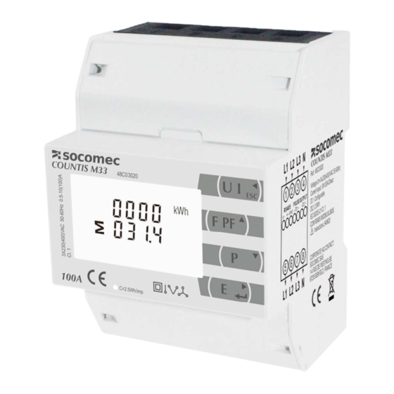
- Page 1 THREE PHASE DIN RAIL ENERGY METER COUNTIS M33 MANUAL V1.0 SOCOMEC CHINA CO., Ltd SOCOMEC CHINA CO., Ltd SOCOMEC CHINA CO., Ltd SOCOMEC CHINA CO., Ltd 溯高美索克曼电气 溯高美索克曼电气( ( ( ( 上海 溯高美索克曼电气 溯高美索克曼电气 上海 上海 上海) ) ) ) 有限公司...
- Page 2 Statement All rights reserved. Without the written permission of Socomec, the contents of any passages and chapters in this manual shall not be copied or reproduced or disseminated in any form. Otherwise, all consequences shall be borne by the violator.
-
Page 3: Table Of Contents
Contents Part 1 Product overview 1.1 Brief Introduction --------------------------------------------------------------------------------------------------------------1 1.2 Product characteristics -------------------------------------------------------------------------------------------------------1 1.3 Application ----- ----------------------------------------------------------------------------------------------------------------2 Part 2 General Specifications 2.1 Specifications-----------------------------------------------------------------------------------------------------------------3 2.2 Accuracy -------------------------------------------------------------------------------------------------------------------------3 2.3 RS485 Communication-------------------------------------------------------------------------------------------------------4 2.4 Environment--------------------------------------------------------------------------------------------------------------------4 2.5 Dimendions---------------------------------------------------------------------------------------------------------------------5 2.6 Wiring Diagram----------------------------------------------------------------------------------------------------------------6 Part 3. Operation Instructions Display and Operation ---------------------------------------------------------------------------------------------------7 Button Definition... - Page 4 Number Entry Procedure 3.3.2 -------------------------------------------------------------------------------------------13 3.3.3 Set Password----------------------------------------------------------------------------------------------------------------14 3.3.4 Modbus Address-----------------------------------------------------------------------------------------------------------15 3.3.5 Baud Rate--------------------------------------------------------------------------------------------------------------------15 3.3.6 Parity--------------------------------------------------------------------------------------------------------------------------16 3.3.7 Stop bit-----------------------------------------------------------------------------------------------------------------------17 3.3.8 Pule Output------------------------------------------------------------------------------------------------------------------17 3.3.9 Pulse Constant--------------------------------------------------------------------------------------------------------------18 3.3.10 Pulse Duration------------------------------------------------------------------------------------------------------------19 3.3.11 Set DIT ---------------------------------------------------------------------------------------------------------------------20 3.3.12 Set backlit lasting time--------------------------------------------------------------------------------------------------21 3.3.13 Set System------------------------------------------------------------------------------------------------------------------22 3.3.14 Clear-------------------------------------------------------------------------------------------------------------------------23 Part 4....
-
Page 5: Part 1 Product Overview
COUNTIS M33 supports max. 100A direct connection, saves the cost and avoid the trouble to connect external CTs, giving the unit a cost-effective and easy operation. Built-in interfaces provides pulse and RS485 Modbus RTU outputs. -
Page 6: Application
Pulse output duration 1.3 Application COUNTIS M33 is a multi-functional three phase energy meter, designed for power system, public facilities, industrial applications and residential power monitoring needs. It can also be used in AC charging piles, solar photovoltaic and other occasions. Its complete communication function makes it very suitable for real-time power monitoring systems. -
Page 7: Part 2 General Specifications
Part 2 General Specifications 2.1 Specifications Voltage: Rated Voltage (Un):3x230(400)V Operational voltage: 80~120% Current: Rated Current (Ib):10A Max Current (Imax): 100A Over current withstand: 0.4% Ib~Imax Over current withstand: 20 Imax for 0.5s Operational frequency:Rated:50/60Hz Range:45-65 Hz Insulation capabilities: AC voltage withstand 4KV/1min Impulse voltage withstand 6kV –... -
Page 8: Rs485 Communication
Apparent power:±1% Active energy:Class1 Reactive energy:Class2 2.3 RS485 Communication Bus Type:RS485 Communication Protocol:Modbus RTU Baud rate: 2400/4800/9600/19200/38400bps Modbus Address:1-247 Bus load:64pcs Communication distance:1000m Parity:EVEN /ODD/NONE Data bit:8 Stop bit:1 2.4 Environment Operating humidity: ≤90% Storage humidity: ≤95% Operating temperature: -25℃~+55℃ Storage temperature:... -
Page 9: Dimendions
Insulating encased meter of protective class: Altitude: ≤2000m 2.5 Dimensions Height: 66 mm Width: 72 mm Length: 100 mm - 5 -... -
Page 10: Wiring Diagram
2.6 Wiring Diagram 3P4W 3P3W 1P2W - 6 -... -
Page 11: Part 3. Operation Instructions
Part 3. Operation Instructions 3.1 Display and Operation When the meter is powered on, the meter will initialize and do self-checking Display as following: Full screen Software version Self-checking finish 3.1.1 Button Definition Selects V and A display screen. In Set-up Mode, it is the “Left” or “Back” button Selects Hz and PF display screen. - Page 12 Phase to neutral voltages(3p4w) Phase to neutral voltages(3p3w) Current on each phase Phase to neutral voltage THD%(3p4w) Current THD% for each phase - 8 -...
-
Page 13: Frequency, Power Factor & Demand
3.2.2 Frequency, Power Factor & Demand Press button : Frequency and Power Factor (total) Power Factor of each phase Maximum Current Demand Maximum Power Demand - 9 -... -
Page 14: Power
3.2.3 Power Press : Instantaneous Active Power in kW Instantaneous Reactive Power in kVAr Instantaneous Volt-amps in KVA Total kW, kVAr, kVA - 10 -... -
Page 15: Energy
3.2.4 Energy Press button : Total active energy in kWh Total reactive energy in kVArh Imported active energy in kWh Exported active energy in kWh - 11 -... -
Page 16: Setting By Button
Imported reactive energy in kVArh Exported reactive energy in kVArh 3.3 Setting by button o enter set-up mode, pressing the button for 3 seconds, until the password screen appears. Setting up is password-protected so you must enter the correct password (default ‘1000’) before processing. -
Page 17: Button Operation
To exit setting-up mode, press repeatedly until the measurement screen is restored. 3.3.1 Button Operation 1. After Entering the Setting manu, use the buttons to select the required item from the menu. Selection does not roll over between bottom and top of list Press to confirm your selection. -
Page 18: Set Password
setting up section, a password must be entered. Digits are set individually, from left to right. The procedure is as follows: The current digit to be set flashes and is set using the Press to confirm each digit setting. The SET indicator appears after the last digit has been set. -
Page 19: Modbus Address
Press to exit the number setting routine and return to the Set-up menu. SET will be removed 3.3.4 Modbus Address (The range is from 001 to 247) From the Set-up menu, use buttons to select the Address ID Press button to enter the selection routine. -
Page 20: Parity
From the Set-up menu, use buttons to select the Baud Rate option. Press to enter the selection routine. The current setting will flash. buttons to choose Baud rate 2.4k. 4.8k, 9.6k, 19.2k, 38.4k 3.3.6 Parity Options: EVEN / ODD / NONE. From the Set-up menu, use buttons to select the Parity option. -
Page 21: Stop Bit
Press to enter the selection routine. The current setting will flash. buttons to choose Parity (EVEN / ODD / NONE) 3.3.7 Stop bit Option:1 or 2. From the Set-up menu, use buttons to select the Stop Bit option. Press to enter the selection routine. -
Page 22: Pulse Constant
defined amount of energy active or reactive. Use this section to set up the pulse output for: Total kWh/ Total kVArh Import kWh/Export kWh Import KVArh/Export KVArh From the Set-up menu, use buttons to select the Pulse output option. Press to enter the selection routine. -
Page 23: Pulse Duration
(It shows 1 impulse = 10kWh/kVArh) From the Set-up menu, use buttons to select the Pulse Rate option. Press to enter the selection routine. The current setting will flash. Note: When it’s dFt, it means 2.5Wh/VArh buttons to choose pulse rate. On completion of the entry procedure, press to confirm the setting and press... -
Page 24: Set Dit
(It shows pulse width of 200ms) From the Set-up menu, use buttons to select the Pulse width option. Press to enter the selection routine. The current setting will flash. buttons to choose pulse width. On Completion of the entry procedure, press to confirm the setting and press to return to the... -
Page 25: Set Backlit Lasting Time
From the set-up menu, use buttons to select the DIT option. The screen will show the currently selected integration time. Press to enter the selection routine. The current time interval will flash buttons to select the time required. Press to confirm the selection. SET indicator will appear. -
Page 26: Set System
Press to enter the selection routine. The current time interval will flash The options can be: 0(always on),5,10,30,60,120minutes buttons to select the time required. Press confirm the set-up, 3.3.13 Set System Use this section to set the type of power supply being monitored. From the Set-up menu, use buttons to select the System option. -
Page 27: Clear
3.3.14 Clear The meter provides a function to reset the maximum demand value of current and power.。 From the Set-up menu, use buttons to select the reset option. Press to enter the selection routine. The MD will flash. Press to confirm the setting and press to return to the main set up menu. -
Page 28: Part 4. . . . Modbus Register Map
Part 4. . . . Modbus resgiter Map Function code to read input parameters Modbus Protocol Input Register Parameter Start Address Ø Ø Ø Parameter Address Hi byte Parameter Number unit (Register) byte 30001 Volts √ √ Phase 1 line to neutral volts. 30003 Volts √... - Page 29 30033 None √ Phase 2 power factor (1). 30035 None √ Phase 3 power factor (1). 30037 Degrees √ √ Phase 1 phase angle. 30039 Degrees √ Phase 2 phase angle. 30041 Degrees √ Phase 3 phase angle. 30043 Volts √...
- Page 30 30101 √ √ √ Total system VA demand. 30103 √ √ √ Maximum total system VA demand. 30105 Amps √ Neutral current demand. 30107 Amps √ Maximum neutral current demand. 30201 Volts √ √ Line 1 to Line 2 volts. 30203 Volts √...
- Page 31 30337 √ √ Line 2 to line 3 volts THD. % 30339 √ √ Line 3 to line 1 volts THD. % 30341 √ √ Average line to line volts THD. % 30343 √ √ √ Total kwh(3) 30345 kvarh √...
- Page 32 Function code to set holding parameter to read holding parameter Modbus Protocol Start Address Paramet Parameter Address Hex Register Valid range Mode High Number Byte Byte Write demand period: 0, 5,8, 10, 15, 20, 30 or 60 minutes, default 60. Setting the period to 0 will cause the demand to show the current parameter value, and demand...
- Page 33 Data Format : Float Write any value to password lock protected registers. Read password lock status: 0 = locked. 1 = unlocked. 40015 Password Lock Reading will also reset the Pass word timeout back to one minute. Length : 4 byte Data Format : Float Write the network port parity/stop bits for MODBUS Protocol, where:...
- Page 34 1--0.01 kWh(kVArh)/imp 2--0.1 kWh(kVArh)/imp 3—1 kWh(kVArh)/imp 4-10 kWh(kVArh)/imp 5-100 kWh(kVArh)/imp Length : 4 byte Data Format : Float Write password for access to protected registers. 40025 Password Length : 4 byte Data Format : Float Write the network port baud rate for MODBUS Protocol, where: 0 = 2400 baud.
- Page 35 4: export active energy, default 5: import reactive energy 6: total reactive energy 8: export reactive energy Length : 4 byte Data Format : Float 00 00 :reset the Maximum demand 461457 30729 Reset Length : 2 byte Data Format: Hex Serial number Length: 4 byte 464513...
Need help?
Do you have a question about the COUNTIS M33 and is the answer not in the manual?
Questions and answers