Table of Contents
Advertisement
Advertisement
Table of Contents

Related Manuals for socomec COUNTIS M43


Summary of Contents for socomec COUNTIS M43
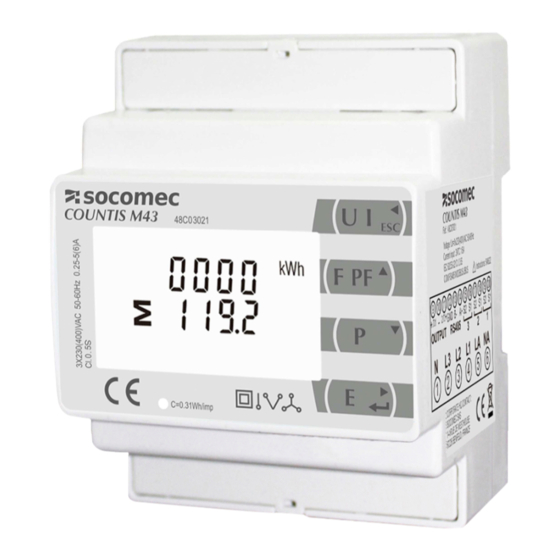
- Page 1 THREE PHASE DIN RAIL ENERGY METER COUNTIS M43 MANUAL V1.0 SOCOMEC CHINA CO., Ltd SOCOMEC CHINA CO., Ltd SOCOMEC CHINA CO., Ltd SOCOMEC CHINA CO., Ltd 溯高美索克曼电气 溯高美索克曼电气( ( ( ( 上海 溯高美索克曼电气 溯高美索克曼电气 上海 上海 上海) ) ) ) 有限公司...
- Page 2 Statement All rights reserved. Without the written permission of Socomec, the contents of any passages and chapters in this manual shall not be copied or reproduced or disseminated in any form. Otherwise, all consequences shall be borne by the violator.
-
Page 3: Table Of Contents
Button Operation 3.3.1 -------------------------------------------------------------------------------------------------------13 Number Entry Procedure 3.3.2 -------------------------------------------------------------------------------------------13 3.3.3 Set Password----------------------------------------------------------------------------------------------------------------14 SOCOMEC CHINA CO., Ltd SOCOMEC CHINA CO., Ltd SOCOMEC CHINA CO., Ltd SOCOMEC CHINA CO., Ltd 溯高美索克曼电气 溯高美索克曼电气( ( ( ( 上海 上海) ) ) ) 有限公司 有限公司... - Page 4 3.3.13 Set DIT ----------------------------------------------------------------------------------------------------------------------21 3.3.14 Set backlit lasting time--------------------------------------------------------------------------------------------------22 3.3.15 Set System------------------------------------------------------------------------------------------------------------------23 3.3.16 Clear-------------------------------------------------------------------------------------------------------------------------24 Part 4. . . . Modbus register Map------------------------------------------------------------------------------------------------25 SOCOMEC CHINA CO., Ltd SOCOMEC CHINA CO., Ltd SOCOMEC CHINA CO., Ltd SOCOMEC CHINA CO., Ltd 溯高美索克曼电气 溯高美索克曼电气( ( ( ( 上海...
-
Page 5: Part 1 Product Overview
Part 1 Product overview 1.1 Brief Introduction COUNTIS M43 measures and displays the characteristics of single phase two wires (1p2w), three phase three wires(3p3w,) and three phase four wires(3p4w) supplies, including voltage, frequency, current, power ,active and reactive energy, imported or exported. Energy is measured in terms of kWh, kVArh. -
Page 6: Application
1.3 Application COUNTIS M43 is a multi-functional three phase energy meter, designed for power system, public facilities, industrial applications and residential power monitoring needs. It can also be used in AC charging piles, solar photovoltaic and other occasions. Its complete communication function makes it very suitable for real-time power monitoring systems. -
Page 7: Part 2 General Specifications
Part 2 General Specifications 2.1 Specifications Voltage::Rated Voltage ( Un) L-N 100 to 276V a.c. (not for 3p3w supplies) 173 to 480V AC. (3p supplies only) Primary Voltage: 20V-500kV Second Voltage:100-500V Auxiliary Supply:85~275V AC / 120~380V DC Current: Primary Current :1-9999A Second Current:1A or 5A Over current withstand: 20 Imax for 0.01s Operational frequency:Rated:50/60Hz... -
Page 8: Rs485 Communication
Active Power:0.5% Reactive Power:±0.5% Apparent power:±0.5% Active energy:Class 0.5S Reactive energy:Class2 2.3 RS485 Communication Bus Type:RS485 Communication Protocol:Modbus RTU Baud rate: 2400/4800/9600/19200/38400bps Modbus Address:1-247 Bus load:64pcs Communication distance:1000m Parity:EVEN /ODD/NONE Data bit:8 Stop bit:1 2.4 Environment Operating humidity: ≤90% Storage humidity: ≤95% Operating temperature:... -
Page 9: Dimendions
Protection against penetration of dust and water: IP51(indoor) Insulating encased meter of protective class: Altitude: ≤2000m 2.5 Dimensions Height:65 mm Width:72 mm Length: 94.5 mm 2.6 Wiring Diagram 3P4W 3P3W 1P2W - 5 -... -
Page 10: Part 3. Operation Instructions
Part 3. Operation Instructions 3.1 Display and Operation When the meter is powered on, the meter will initialize and do self-checking Display as following: Full screen Software version Self-checking finish 3.1.1 Button Definition Selects V and A display screen. In Set-up Mode, it is the “Left” or “Back” button Selects Hz and PF display screen. - Page 11 Phase to neutral voltages(3p4w) Phase to neutral voltages(3p3w) Current on each phase Neutral current Phase to neutral voltage THD%(3p4w) - 7 -...
-
Page 12: Frequency, Power Factor & Demand
Current THD% for each phase 3.2.2 Frequency, Power Factor & Demand Press button : Frequency and Power Factor (total) Power Factor of each phase Maximum Current Demand - 8 -... -
Page 13: Power
Maximum Power Demand 3.2.3 Power Press : Instantaneous Active Power in kW Instantaneous Reactive Power in kVAr Instantaneous Volt-amps in KVA - 9 -... -
Page 14: Energy
Total kW, kVAr, kVA 3.2.4 Energy Press button : Total active energy in kWh Total reactive energy in kVArh Imported active energy in kWh - 10 -... -
Page 15: Setting By Button
Exported active energy in kWh Imported reactive energy in kVArh Exported reactive energy in kVArh 3.3 Setting by button To enter set-up mode, pressing the button for 3 seconds, until the password screen appears. Setting up is password-protected so you must enter the correct password (default ‘1000’) before processing. -
Page 16: Button Operation
To exit setting-up mode, press repeatedly until the measurement screen is restored. 3.3.1 Button Operation 1. After Entering the Setting manu, use the buttons to select the required item from the menu. Selection does not roll over between bottom and top of list Press to confirm your selection. -
Page 17: Number Entry Procedure
On completion of all set-up, press repeatedly until the measurement screen is restored. 3.3.2Number Entry Procedure When setting up the unit, some screens require the entering of a number. In particular, on entry to the setting up section, a password must be entered. Digits are set individually, from left to right. The procedure is as follows: The current digit to be set flashes and is set using the Press... -
Page 18: Modbus Address
to set the first digit and press confirm your selection. The next digit will flash. Press to exit the number setting routine and return to the Set-up menu. SET will be removed 3.3.4 Modbus Address (The range is from 001 to 247) From the Set-up menu, use buttons to select the Address ID... -
Page 19: Baud Rate
buttons to choose Modbus Address(001 to 247) 3.3.5 Baud Rate Options: 2.4k, 4.8k, 9.6k, 19.2k, 38.4k. From the Set-up menu, use buttons to select the Baud Rate option. Press to enter the selection routine. The current setting will flash. buttons to choose Baud rate 2.4k. 4.8k, 9.6k, 19.2k, 38.4k 3.3.6 Parity... -
Page 20: Stop Bit
From the Set-up menu, use buttons to select the Parity option. Press to enter the selection routine. The current setting will flash. buttons to choose Parity (EVEN / ODD / NONE) 3.3.7 Stop bit Option:1 or 2. From the Set-up menu, use buttons to select the Stop Bit option. -
Page 21: Ct Setting
Press to enter the selection routine. The current setting will flash. buttons to choose Stop Bit (2 or 1) Note: Default is 1, and only when the parity is NONE that the stop bit can be changed to 2. 3.3.8 CT Setting The CT option sets the secondary current (CT2 1A or 5A) of the current transformer (CT) that wires to the meter. -
Page 22: Pt Setting
Example: If set the ratio to be 100,it means the primary current equals secondary currentx100 3.3.9 PT Setting The PT option sets the secondary voltage (PT2 100 to 500V) of the Voltage transformer(PT) that wires to the meter. From the Set-up menu, use buttons to select the PT option. -
Page 23: Pule Output
3.3.10 Pulse Output This option allows you to configure the pulse output. The output can be set to provide a pulse for a defined amount of energy active or reactive. Use this section to set up the pulse output 1—Units: Total kWh, Total kVArh From the Set-up menu, use buttons to select the Pulse output option. -
Page 24: Pulse Duration
(It shows 1 impulse = 10kWh/kVArh) From the Set-up menu, use buttons to select the Pulse Rate option. Press to enter the selection routine. The current setting will flash. Use Pulse buttons to choose the Constant. Press to confirm the setting and press to return to the main set up menu. -
Page 25: Set Dit
(It shows pulse width of 200ms) From the Set-up menu, use buttons to select the Pulse width option. Press to enter the selection routine. The current setting will flash. buttons to choose pulse width. On Completion of the entry procedure, press to confirm the setting and press to return to the... -
Page 26: Set Backlit Lasting Time
From the set-up menu, use buttons to select the DIT option. The screen will show the currently selected integration time. Press to enter the selection routine. The current time interval will flash buttons to select the time required. ress to confirm the selection. SET indicator will appear. -
Page 27: Set System
Press to enter the selection routine. The current time interval will flash The options can be: 0(always on),5,10,30,60,120minutes buttons to select the time required. Press confirm the set-up, 3.3.15 Set System Use this section to set the type of power supply being monitored. From the Set-up menu, use buttons to select the System option. -
Page 28: Clear
3.3.16 Clear The meter provides a function to reset the maximum demand value of current and power.。 From the Set-up menu, use buttons to select the reset option. Press to enter the selection routine. The MD will flash. Press to confirm the setting and press to return to the main set up menu. -
Page 29: Part 4. . . . Modbus Register Map
Part 4. . . . Modbus register Map Function code to read input parameters Input Register Parameter 寄存器首地址 寄存器首地址 寄存器首地址 寄存器首地址 Ø Ø Ø Address (Register Data Length of the High Parameter unit byte Format Byte Byte Phase 1 line to neutral volts. 30001 Float √... - Page 30 Phase 3 volt amps. 30023 Float √ Phase 1 Reactive Power 30025 Float √ √ Phase 2 Reactive Power 30027 Float √ Phase 3 Reactive Power 30029 Float √ Phase 1 power factor (1). 30031 Float None √ √ Phase 2 power factor (1). 30033 Float None...
- Page 31 Frequency of supply voltages. 30071 Float √ √ √ Total Import kWh 30073 Float √ √ √ Total Export kWh. 30075 Float √ √ √ Total Import kVArh . 30077 Float kVArh √ √ √ Total Export kVArh . 30079 Float kVArh √...
- Page 32 Average line to line volts. 30207 Float √ √ 30225 Neutral current. Float √ Phase 1 L/N volts THD 30235 Float √ √ Phase 2 L/N volts THD 30237 Float √ Phase 3 L/N volts THD 30239 Float √ Phase 1 Current THD 30241 Float √...
- Page 33 Average line to line volts THD. 30341 Float √ √ % Total kwh(3) 30343 Float √ √ √ Total kvarh(3) 30345 Float kVArh √ √ √ L1 import kwh 30347 Float √ √ √ L2 import kwh 30349 Float √ √...
- Page 34 L1 total kvarh (3) 30377 Float kVArh √ √ √ L2 total kvarh (3) 30379 Float kVArh √ √ L3 total kvarh (3) 30381 Float kVArh √ √ resettable total active energy 30385 Float √ √ √ resettable total reactive energy 30387 Float kVArh...
- Page 35 demand to show the Current parameter value and demand max to show the maximum parameter value since last demand reset. Length : 4 byte Data Format : Float Write system type: 3p4w = 3, 3p3w = 2 & 1p2w= 1 Requires password, see parameter 13 40011 System Type...
- Page 36 and odd parity.3 = Two stop bits and no parity. Requires a restart to become effective. Length : 4 byte Data Format : Float Write the network port node address: 1 to 247 for MODBUS Protocol, default 1. Requires a restart to become effective. 40021 Network Node Length : 4 byte...
- Page 37 Write the baud rate for MODBUS Protocol, where: 0 = 2400 baud. 1 = 4800 baud. 2 = 9600 baud, default. 40029 Baud Rate 3 = 19200 baud. 4 = 38400 baud. Length : 4 byte Data Format : Float CT Ratio range:1~2000 CT Ratio= primary current /secondary current Length : 4 byte...
- Page 38 Length : 4 byte Data Format : Float 00 00 :reset the Maximum demand 00 03:reset the resettable energy 461457 30729 Reset Length : 2 byte Data Format: Hex Serial number Length: 4 byte 464513 32257 Serial number Data Format: unsigned int32 Note: Only read - 34 -...
Need help?
Do you have a question about the COUNTIS M43 and is the answer not in the manual?
Questions and answers