
Related Manuals for SCHUNK KSP3-IM 100


Summary of Contents for SCHUNK KSP3-IM 100
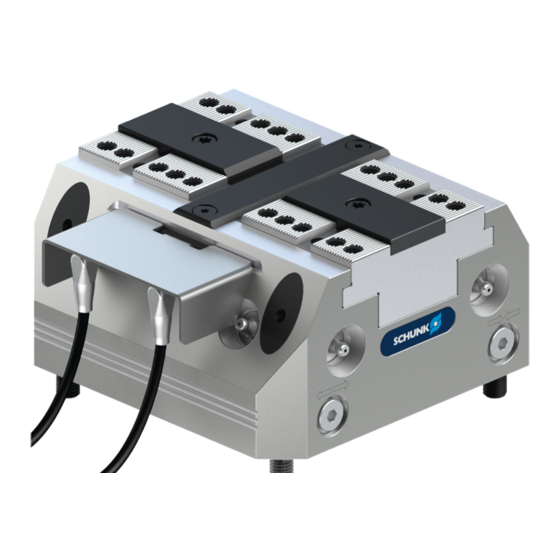
- Page 1 Translation of Original Operating Manual TANDEM Clamping Block KSP3-IM, KSP3-LH-IM Assembly and Operating Manual...
- Page 2 Imprint Imprint Copyright: This manual is protected by copyright. The author is SCHUNK GmbH & Co. KG. All rights reserved. Technical changes: We reserve the right to make alterations for the purpose of technical improvement. Document number: 1474090 Version: 03.00 | 16/12/2022 | en...
-
Page 3: Table Of Contents
Table of Contents Table of Contents General........................ 5 About this manual.................... 5 1.1.1 Presentation of Warning Labels............... 5 1.1.2 Applicable documents ................ 5 1.1.3 Sizes ...................... 6 1.1.4 Variants.................... 6 Warranty ...................... 6 Scope of Delivery .................... 6 Accessories...................... 6 Basic safety notes .................... 7 Intended use ...................... - Page 4 Table of Contents Maintenance and care .................... 33 Notes........................ 33 Maintenance and lubrication intervals .............. 33 Greasing areas/lubricants .................. 33 7.3.1 Lubrication ..................... 34 7.3.2 Leak test.................... 40 7.3.3 Assembly device.................. 41 Sealing kits, accessory packs and parts lists............. 42 Sealing kit lists.................... 42 Accessory packs ....................
-
Page 5: General
1.1.2 Applicable documents • General terms of business * • Catalog data sheet of the purchased product * The documents labeled with an asterisk (*) can be downloaded from schunk.com. 03.00 | KSP3-IM, KSP3-LH-IM | TANDEM Clamping Block | en | 1474090... -
Page 6: Sizes
General 1.1.3 Sizes This operating manual applies to the following sizes: • KSP3 IM 100, 140, 160, 200, 250, 315 • KSP3-LH IM 100, 140, 160, 200, 250, 315 1.1.4 Variants This manual applies to the following variants: • Clamping force amplification for O.D. clamping (AS) •... -
Page 7: Basic Safety Notes
• Structural changes should only be made with the written approval of SCHUNK. 03.00 | KSP3-IM, KSP3-LH-IM | TANDEM Clamping Block | en | 1474090... -
Page 8: Spare Parts
Use of unauthorized spare parts Using unauthorized spare parts can endanger personnel and damage the product or cause it to malfunction. • Use only original spare parts or spares authorized by SCHUNK. 2.5 Use of special chuck jaws Requirements of the chuck jaws When using special chuck jaws, please observe the following rules: •... -
Page 9: Personnel Qualification
Basic safety notes 2.7 Personnel qualification Inadequate qualifications of the personnel If the personnel working with the product is not sufficiently qualified, the result may be serious injuries and significant property damage. • All work may only be performed by qualified personnel. •... -
Page 10: Notes On Safe Operation
Basic safety notes 2.9 Notes on safe operation Incorrect handling of the personnel Incorrect handling and assembly may impair the product's safety and cause serious injuries and considerable material damage. • Avoid any manner of working that may interfere with the function and operational safety of the product. -
Page 11: Disposal
Basic safety notes 2.12 Disposal Handling of disposal The incorrect handling of disposal may impair the product's safety and cause serious injuries as well as considerable material and environmental harm. • Follow local regulations on dispatching product components for recycling or proper disposal. 2.13 Fundamental dangers General •... -
Page 12: Protection Against Dangerous Movements
Basic safety notes 2.13.3 Protection against dangerous movements Unexpected movements Residual energy in the system may cause serious injuries while working with the product. • Switch off the energy supply, ensure that no residual energy remains and secure against inadvertent reactivation. •... - Page 13 Basic safety notes WARNING Risk of injury from falling parts during transport, assembly and disassembly of the product and its accessories. Use suitable load handling equipment for transport • Do not remain in the danger zone • Wear protective equipment (protective shoes) •...
-
Page 14: Technical Data
Technical data 3 Technical data Installation position Operating temperature +5 °C to +60 °C Noise emission [dB(A)] ≤ 70 Pressure medium Compressed air, compressed air quality according to ISO 8573-1:7 4 4 Max. speed of rotation 100 RPM Size Stroke/ Clampi Additional Standard/AS Repeat max. - Page 15 Technical data KSP3 IM/KSP3-LH IM ensi Ø C 6H7 x 12 8H7 x 14 8H7 x 14 8H7 x 14 10H7 x 20 10H7 x 20 29.5 64.5 45.5 64.5 34.5 51.8 59.7 92.6 139.6 69.2 72.7 82.2 90.2 98.2 13.5 17.5 15.5...
- Page 16 Technical data Optional Z variant ±0.01 mm to clamping center Clamping sleeve ±0.04 mm to clamping center Clamping sleeve fitting screw ±0.02 mm to clamping center 03.00 | KSP3-IM, KSP3-LH-IM | TANDEM Clamping Block | en | 1474090...
-
Page 17: Tightening Torques For Screws
Tightening torques for screws 4 Tightening torques for screws Tightening torques for mounting the clamping system on the machine table (screw quality 10.9) Screw size M4 M5 M6 M8 M10 M12 M14 M16 M18 M20 M22 M24 Admissible torque 120 160 200 290 400 500 (Nm) Tightening torques for mounting top jaws on the TANDEM clamping force block (screw quality 12.9) -
Page 18: Assembly
Assembly 5 Assembly The numbers shown for individual components refer to the illustrations for assembly or connections of the clamping force } 9 [ / 46] block and to the "Drawings" chapter. WARNING Danger of crushing due to the product approaching the machine table during assembly. -
Page 19: Mounting The Clamping Force Block On The Base Plate
Assembly NOTE • For vertical installation, the openings of the coolant drain (V) must always face downwards • Surface >>X<< is parallel to the guideway of the base jaws (item 2) in order to be able to align the clamping force block on the machine table or check the positioning. - Page 20 Assembly NOTE If the clamping force block and base plate are ordered separately, the screws, O-rings and clamping sleeves for assembling the parts are included in the accessory kit that comes with the clamping force block. • Do not open the connections on the front of the clamping force block (I, II), or seal them with suitable dummy plugs (M5 or G1/8").
-
Page 21: Connecting The Clamping Block
Assembly 5.3 Connecting the clamping block OPEN (front) CLOSED (front) OPEN (bottom) CLOSED (bottom) Coolant drainage/connection for air purge (front) No use No use No use No use Bottom connection for coolant drain or use for air purge Bottom connection for lubrication (one-sided supply, left) Bottom connection for lubrication (one-sided supply, right) No use Hose-free direct connection... -
Page 22: Supply Lines
Assembly 5.3.1 Supply lines The clamping force block has four air connections: I, II, III, IV. Two connections for OPEN (I and III) and two connections for CLOSE (II and IV). The application determines which of the two air connections must be opened for actuation: •... -
Page 23: Monitoring Of The Jaw Position Via Inductive Proximity Switches
The monitoring result is: The clamping force block is open or closed (for I.D. or O.D. clamping depending on the application). • Information on handling sensors is available at schunk.com or from SCHUNK contact persons. • Technical data for the sensors can be found in the data sheets (included in the scope of delivery or at schunk.com). -
Page 24: Construction Concept And Dimensions Of Inductive Proximity Switches With Screw-On Connection Cable
Assembly 5.4.1 Construction concept and dimensions of inductive proximity switches with screw-on connection cable Connection colors Pin 1: Brown Pin 3: Blue Pin 4: Black IN-S-M8-1 IN-S-M8-2 IN-S-M8-3 Size M8 x 1 x 40 mm M5 x 0.5 x 41 mm M8 x 1 x 55 mm Switching function Closer... -
Page 25: Assembly And Adjustment Of The Proximity Switches
Assembly 5.4.2 Assembly and adjustment of the proximity switches For TANDEM KSP3-IM/KSP3-LH-IM, two inductive proximity switches have been fitted. The proximity switches can be moved on the retaining plate (item 12) so that the switching point can be individually adjusted. The proximity switches are used for monitoring the jaw stroke end position for O.D. -
Page 26: Circuit And Functional Diagram For External Workpiece Clamping
Assembly Test the function by clamping and opening the clamping system. If necessary, adjust the switching position. Then link the plug connection between the proximity switch and connection cable. NOTE The sensor head of the proximity switches may not touch the base jaws under any circumstances during operation. - Page 27 Assembly Circuit diagram and monitoring/control functions for external workpiece clamping Circuit diagram proximity switch proximity switch Signal output Jaw end position open Clamping position Jaw end position closed Jaw end position on clamping force block open Clamping position Jaw end position closed Clamping force block closed Fig.°5 Circuit diagram for external workpiece clamping 03.00 | KSP3-IM, KSP3-LH-IM | TANDEM Clamping Block | en | 1474090...
- Page 28 Assembly Functional diagram for O.D clamping »S1« Monitoring the jaw »S2« Monitoring troke end position for of the clamping O.D. and I.D. clamping position Stroke end position open Edges in front and behind depression serve as position transducers Raised intermediate rail as position transducer Jaw end position »Open«...
-
Page 29: Circuit And Functional Diagram For Internal Workpiece Clamping
Assembly 5.4.4 Circuit and functional diagram for internal workpiece clamping Circuit diagram and monitoring/control functions for internal workpiece clamping The circuit diagram and the functional diagram show the recommended settings of the proximity switches for monitoring "End position closed" and "Clamping position reached." The circuit diagram can also be adjusted for monitoring "Stroke end position open"... - Page 30 Assembly Functional diagram for I.D clamping Stroke end position closed Jaw end position »Open« S1 and S2 adjusted just in front of the signal output »S1« assigned signal »S1« assigned signal output »1« LED lit output »1« LED lit Clamping position Clamping position S2 adjusted just above the switching point »S1«...
-
Page 31: Troubleshooting
Check maintenance unit, perform maintenance Place oiler closer to clamping system Set required oil level Chuck piston screw broken Send clamping system to SCHUNK for repairs or (overload) disassemble clamping system and repair using original SCHUNK spare parts Piston rod or piston rod screw... - Page 32 Troubleshooting Clamping force block does not complete stroke Possible cause Solution(s) Chips or dirt between covering Unscrew the covering strip (item 8) and remove chips and strip and base jaws dirt Clamping force getting weaker Possible cause Solution(s) Clamping force block not Check connection and seal screws;...
-
Page 33: Maintenance And Care
Replacement of the housing and base jaws The base jaws and the guides in the housing are matched to each other. To replace these parts, send the entire product to SCHUNK with a repair order. Maintenance variant with clamping force maintenance (AS) The cylinder piston must be disassembled or assembled using a disassembly and assembly device. - Page 34 Alternative lubricant LINOMAX plus can also be used as an alternative to microGleit LP 410. However, the specified clamping forces exclusively refer to the microGleit LP 410 used by SCHUNK. For LINOMAX plus, the clamping forces can be lower. 7.3.1 Lubrication CAUTION...
- Page 35 Maintenance and care Central lubrication • To use central lubrication, the set- screws of the factory sealed connections (6, 7) must be removed. • For proper lubrication, both supply lines must be connected. • The central lubrication system must be suitable for greases of NLGI 2 classification.
- Page 36 Maintenance and care Disassembly Before disassembling the product, switch off the machine and secure it against being switched on again. Then remove all compressed air lines. No residual energy may be left in the product. • Disassemble the supply cable to the pin terminal of the inductive proximity switches on the separable elbow fitting •...
- Page 37 Maintenance and care • Remove screws (item 64) and take off the cover strip (item 8) • Remove screws (item 66) and take off the guide strip (item 6) Remove screws (item 65) and pull out cover (item 5) together with O-ring (item 45) and flat gaskets (item 48) out of the housing.
- Page 38 Maintenance and care Variant without clamping force maintenance • Unscrew the screw (item 69) by holding it against the cylinder piston (item 4) • Pull the chuck piston (item 3) out of the housing via its extraction thread • Push the cylinder piston together with the quad ring (item 40) out of the housing.
- Page 39 Maintenance and care Variant with clamping force maintenance (AS) Warning! Risk of injury due to spring forces! The cylinder piston and cover are under spring tension! • Clamp the product between the base jaws (item 2) and the mounting cover (item 200) using a suitable device (e.g.
-
Page 40: Leak Test
Maintenance and care 7.3.2 Leak test The following components are required to check for leaks: Pressure gauge, shut-off valve, supply line and quick coupling. • Check for tightness in the clamping system in the OPEN and CLOSED positions 1. Connect the components to the open CLOSED connection in the following order: Pressure gauge - shut-off valve - quick coupling - supply line 2. -
Page 41: Assembly Device
Maintenance and care 7.3.3 Assembly device Dimension Sizes Ø d1 97.5 137.5 155.5 195.5 Ø d2 Ø d3 Ø d4 Ø d5 10.5 38.9 45.5 93.8 38.9 49.8 93.8 43.5 63.5 91.5 19.4 60.5 76.5 68.3 19.4 76.5 68.3 34.3 45.5 93.8 26.8... -
Page 42: Sealing Kits, Accessory Packs And Parts Lists
Sealing kits, accessory packs and parts lists 8 Sealing kits, accessory packs and parts lists When ordering spare parts, the type , size and, if possible, the serial number of the clamping force block must always be stated to avoid delivery mistakes. -
Page 43: Parts Lists
Sealing kits, accessory packs and parts lists 8.3 Parts lists Parts list "Standard stroke" and "Long stroke" variants Item Description Quanti Body >Housing< ● Base jaw ● Chuck piston ● Cylinder piston ● Cover ● Guide strip ● Covering strip ●... - Page 44 Sealing kits, accessory packs and parts lists Screw ● Set-screw ● ● Cylindrical screw ● Washer ● Cylindrical screw ● ● Plug ● ● Fitting screw ● ● O-ring DIN ISO 3601 ● ● ● Screw ● ● Clamping sleeve ●...
-
Page 45: Proximity Switches And Supply Cables For Single Or Replacement Orders
Sealing kits, accessory packs and parts lists 8.4 Proximity switches and supply cables for single or replacement orders The IN inductive proximity switch IN consists of an angular supply cable type KA-M12 and self-assembly plug connector. Inductive proximity switch IN – M8 plug connection Designation ID number IN S-M8-1... -
Page 46: Assembly Drawing
Assembly drawing 9 Assembly drawing Only for variant "AS" Centering with fitting screw Centering with clamping sleeves Centering with cylindrical pins (Z variant) 03.00 | KSP3-IM, KSP3-LH-IM | TANDEM Clamping Block | en | 1474090... -
Page 47: Translation Of The Original Declaration Of Incorporation
Directive 2006/42/EG, Annex II, Part 1.B of the European Parliament and of the Council on machinery. Manufacturer/ H.-D. SCHUNK GmbH & Co. Spanntechnik KG Distributor Lothringer Str. 23 D-88512 Mengen We hereby declare that on the date of the declaration the following partly completed machine complied with all basic safety and health regulations found in the directive 2006/42/EC of the European Parliament and of the Council on machinery. -
Page 48: Appendix On Declaration Of Incorporation, As Per 2006/42/Ec, Annex Ii, No. 1 B
Appendix on Declaration of Incorporation, as per 2006/42/EC, annex II, No. 1 B 11 Appendix on Declaration of Incorporation, as per 2006/42/EC, annex II, No. 1 B 1. Description of the basic safety and health protection requirements, as per 2006/42/EC, annex I, that apply to and are fulfilled for the scope of the incomplete machine: Product designation TANDEM clamping force block, pneumatic (with inductive proximity switches) - Page 49 Appendix on Declaration of Incorporation, as per 2006/42/EC, annex II, No. 1 B Protection against mechanical hazards 1.3.4 Risks due to surfaces, edges or angles 1.3.5 Risks related to combined machinery 1.3.6 Risks related to variations in operating conditions 1.3.7 Risks related to moving parts 1.3.8 Choice of protection against risks arising from moving parts...
- Page 50 Appendix on Declaration of Incorporation, as per 2006/42/EC, annex II, No. 1 B Maintenance 1.6.5 Cleaning of internal parts Information 1.7.1 Information and warnings on the machinery 1.7.1.1 Information and information devices 1.7.1.2 Warning devices 1.7.2 Warning of residual risks 1.7.3 Marking of machinery 1.7.4...
- Page 52 Translation of Original Operating Manual H.-D. SCHUNK GmbH & Co. Spanntechnik KG Lothringer Str. 23 D-88512 Mengen Tel. +49–7572-7614-0 Fax +49-7572-7614-1099 info@de.schunk.com schunk.com Folgen Sie uns I Follow us...
Need help?
Do you have a question about the KSP3-IM 100 and is the answer not in the manual?
Questions and answers