
Related Manuals for SCHUNK PZH-plus 30


Summary of Contents for SCHUNK PZH-plus 30
- Page 1 Original operating manual 3-finger centric gripper PZH-plus 020-075 Assembly and Operating Manual Superior Clamping and Gripping...
- Page 2 Imprint Copyright: This manual remains the copyrighted property of SCHUNK GmbH & Co. KG. It is solely sup- plied to our customers and operators of our products and forms part of the product. This documentation may not be duplicated or made accessible to third parties, in particular com- petitive companies, without our prior permission.
-
Page 3: Table Of Contents
Table of contents Table of contents 1 General ..........................5 1.1 About this manual ......................5 1.1.1 Presentation of Warning Labels ................5 1.1.2 Applicable documents................... 6 1.1.3 Sizes ........................6 1.2 Warranty ..........................6 1.3 Scope of delivery ........................ 6 1.3.1 Accessory pack ....................... - Page 4 Table of contents 5.1 Connections ........................18 5.1.1 Mechanical connection ..................18 5.1.2 Air connection ..................... 20 5.2 Mounting the sensor ....................... 22 5.2.1 Overview of sensors .................... 22 5.2.2 IN 80 inductive proximity switch ................ 23 5.2.3 MMS 22 magnetic switch ................... 25 5.2.4 MMS-P programmable magnetic switch ............
-
Page 5: General
General General About this manual This manual contains important information for a safe and appropri- ate use of the product. This manual is an integral part of the product and must be kept ac- cessible for the personnel at all times. Before starting work, the personnel must have read and understood this operating manual. -
Page 6: Applicable Documents
1.1.3 Sizes This operating manual applies to the following sizes: • PZH-plus 20 • PZH-plus 30 • PZH-plus 50 • PZH-plus 75 Warranty If the product is used as intended, the warranty is valid for 24 months from the ex-works delivery date under the following conditions: •... -
Page 7: Accessories
For information about which accessories can be used with the ap- propriate product version see catalog. 1.4.1 Seal kit ID.-No. of the seal kit Seal kit for ID number PZH-plus 20 5522219 PZH-plus 30 5522220 PZH-plus 50 5522221 PZH-plus 75 5522222 Contents of the sealing kit, ( 8, Page 40). -
Page 8: Basic Safety Notes
• Constructional changes may only be done with SCHUNK's permis- sion. Spare parts Use of unauthorised spare parts Using unauthorised spare parts can endanger personnel and damage the product or cause it to malfunction. • Use only original spare parts or spares authorised by SCHUNK. 02.00|PZH-plus 020-075|en... -
Page 9: Gripper Fingers
Basic safety notes Gripper fingers Requirements for the gripper fingers Stored energy within the product creates the risk of serious injuries and significant property damage. • Arrange the gripper fingers in a way that the product reaches ei- ther the position "open" or "closed" in a de-energized state. •... -
Page 10: Personal Protective Equipment
Basic safety notes avoid possible dangers and know the relevant standards and regula- tions. Pneumatics specialist Pneumatics specialists have been trained for this particular area of responsibility and know the relevant standards and regulations. Hydraulic specialist Hydraulic specialists have been trained for this particular area of re- sponsibility and knows the relevant standards and regulations. -
Page 11: Notes On Safe Operation
Basic safety notes Notes on safe operation Incorrect handling of the personnel Incorrect handling and assembly may impair the product's safety and cause serious injuries and considerable material damage. • Avoid any manner of working that may interfere with the function and operational safety of the product. -
Page 12: Disposal
Basic safety notes 2.12 Disposal Handling of disposal The incorrect handling of disposal may impair the product's safety and cause serious injuries as well as considerable material and envi- ronmental harm. • Follow local regulations on dispatching product components for recycling or proper disposal. -
Page 13: Protection During Commissioning And Operation
Basic safety notes 2.13.2 Protection during commissioning and operation Falling or violently ejected components Falling and violently ejected components can cause serious injuries and even death. • The danger zone must be cordoned off by a protective barrier. • Never step into the danger zone during operation. 2.13.3 Protection against dangerous movements Unexpected movements... -
Page 14: Protection Against Electric Shock
Basic safety notes 2.13.4 Protection against electric shock Possible electrostatic energy Components or assembly groups may become electrostatically charged. When the electrostatic charge is touched, the discharge may trigger a shock reaction leading to injuries. • The operator must ensure that all components and assembly groups are included in the local equipotential bonding in accord- ance with the applicable regulations. - Page 15 Products with a mechanical gripping force maintenance can, during energy supply failure, still move independently in the direction spec- ified by the mechanical gripping force maintenance. • Secure the end positions of the product with SCHUNK SDV-P pressure maintenance valves. 02.00|PZH-plus 020-075|en...
-
Page 16: Technical Data
Technical data Technical data Pressure medium Compressed air, compressed air quality according to ISO 8573- 1:7 4 4 Nominal working pressure [bar] Min. pressure [bar] Max. pressure [bar] Pressure range for 0,5 – 1 air purge [bar] Noise emission [dB(A)] ≤... -
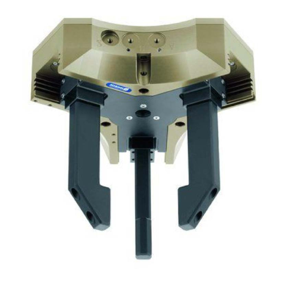
Page 17: Design And Description
Design and description Design and description Configuration 3-finger centric gripper Housing Air purge connection Main air connections Base jaws Description Universal centric gripper with high gripping force and maximum mo- ments due to multi-tooth guidance 02.00|PZH-plus 020-075|en... -
Page 18: Assembly
Assembly Assembly Connections 5.1.1 Mechanical connection Levelness of the The values apply to the whole mounting surface to which the product mounting surface is mounted. Requirements for levelness of the mounting surface (Dimensions in mm) Diameter Permissible unevenness < 100 <... - Page 19 Assembly Mounting The module can be mounted from the front or the rear. Mounting from the rear Finger mounting Centering sleeves Mounting from the front Centering sleeves The centering sleeves (2 / 3) are included in the accessory pack. Mounting material Size Thread diameter and max.
-
Page 20: Air Connection
Assembly 5.1.1.1 Mounting of the gripper by using a spring loaded pressure-piece CAUTION The spring-loaded pressure piece is under spring tension. The pressure piece can fly out in an uncontrolled fashion and cause contusions. • During assembly or disassembly, be especially careful with the springs. - Page 21 Assembly Air connection Item Connection Hose connection (A = open, B = close) Air purge connection Hose-free direct connection (a = open, b = close) Direct connection for air purge • Only open the air connections required. • For hose-free direct connections, use the O-rings from the acces- sory pack.
-
Page 22: Mounting The Sensor
– The assembly and operating manual and the catalogue data sheet are included in the scope of delivery and can be down- loaded from www.schunk.com. • If you require further information on sensor operation, contact your SCHUNK contact person or download information from our homepage. 5.2.1 Overview of sensors... -
Page 23: In 80 Inductive Proximity Switch
Assembly 5.2.2 IN 80 inductive proximity switch Connection example for IN 80 brown black blue The inductive proximity switches used are equipped with reverse po- larity protection and are short-circuit-proof. Make sure that you handle the proximity switches properly: • Do not pull on the cable. •... - Page 24 Assembly Mounting kit To use the inductive sensor, the gripper has to be retrofitted with a special mounting kit. This mounting kit is available from SCHUNK for the models below. Installation of the proximity switch 1 Push the T-nut (4) into the gripper slot (7).
-
Page 25: Mms 22 Magnetic Switch
Assembly 5.2.3 MMS 22 magnetic switch NOTICE Risk of damage to the sensor during assembly! • Observe a maximum tightening torque of 10 Ncm for the set- screws. NOTE Ferromagnetic material changes the switching positions of the sen- sor. For example: Adapter plate made of ordinary steel. At ferromagnetic adapter plates: •... - Page 26 Assembly Gripper open: 1 Set the gripper to the "Open" position. 2 Push the magnetic switch 1 (1) into the groove until it stops at the end of the groove. 3 Pull the magnetic switch 1 (1) back again slowly until it switches. 4 Tighten the set-screw (3) to clamp the magnetic switch 1 (1) in this position in the groove.
-
Page 27: Mms-P Programmable Magnetic Switch
Assembly 5.2.4 MMS-P programmable magnetic switch NOTE The MMS-P can only cover the whole range of stroke in the PZH-plus series for PZH-plus 20 and 30. Magnetic switch MMS-P 22 Mounting screw Teach-button Center sensor elements LED display LED display Ribs for cable tires Connection diagram PNP-4 conductor (MMS-P 22) Types available for order (see catalog):... - Page 28 Assembly Mounting of the sensor NOTICE Sensor can be damaged during assembly. • Do not exceed the maximum tightening torque of 10 Ncm for the set screws! NOTE Ferromagnetic material changes the switching positions of the sensor (e.g. Adapter plate made of ordinary steel). For ferromagnetic adapter plates: •...
- Page 29 Dimensions I1 / I2 Size [mm] [mm] PZH-plus 20 49.1 58.0 PZH-plus 30 62.8 71.7 Setting up the swit- ching points 1 Press the Teach button (4) for 2 seconds. After 2 seconds LED 1 (3) is flashing. 2 Move the gripper into position 1 (e.g. "open").
- Page 30 (i.e. by shielding). Frequent types of disturbances are change in temperature and electro-magnetic influences. Within the closest fine-teach mode, SCHUNK cannot guarantee EMC- compatibility any more. The hysteresis adjustment is used for the manual adjustment of the switching points (if necessary).
- Page 31 Assembly 1 Press the "Teach" button (4) for 5 seconds. LED 1 (3) flashes from 2nd to 5th second. LED 1 goes off after 5 sec. 2 Release the "Teach" button. 3 Move the gripper to the "switch-off point for switching point 1" position.
-
Page 32: Troubleshooting
Unused air connections open. Close unused air connections. Flow control valve closed. Open the flow control valve. Component part defective. Replace component or send it to SCHUNK for repair. Product does not travel through the entire stroke Possible cause Corrective action Dirt deposits between basic jaws and guid- Disassemble and clean the product. -
Page 33: Product Opens Or Closes Abruptly
To much grease in the mechanical movement Clean and lubricate product. space. ( 7, Page 35) Pressure drops below minimum. Check air supply. Link Pneumatischer Anschluss Component part defective. Replace component or send it to SCHUNK for repair. 02.00|PZH-plus 020-075|en... -
Page 34: Product Does Not Achieve The Opening And Closing Times
Troubleshooting Product does not achieve the opening and closing times Possible cause Corrective action Compressed air lines are not installed optimal- If present: Open the flow control couplings on the module to the maximum that the move- ment of the jaws occurs without bouncing and hitting. -
Page 35: Maintenance
Exchange of housing and base jaws The base jaws and the guidance in the housing are matched. To ex- change these parts, send the product with a repair order to SCHUNK or order the housing with the base jaws as a set. -
Page 36: Disassembly Of The Module
Maintenance Disassembly of the module Position of the position numbers ( 8, Page 40) Assembly tools are needed for disassembly ( 7.4.1, Page 37)/( 7.4.2, Page 38). WARNING Risk of injury from uncontrolled movements! If the energy supply is switched on or residual energy remains in the system, parts may move unexpectedly and cause serious injuries. -
Page 37: Assembly Tool X
Maintenance 11 Remove the lock nut (16) with the assembly tool (Y). 12 Pull the base jaw (2) with the piston (3) out of the housing (1) and remove the piston (3) from the base jaw (2). 13 Remove the piston rod clamping nut (7) with the assembly tool (X) and take out the piston rod (5). -
Page 38: Assembly Tool Y
Maintenance 7.4.2 Assembly tool Y Assembly tool Y, part 1 (Dimensions in mm) PZH- plus 3.0 13.0 17.0 1.0 12.0 12.0 1.6 12.0 M5 11.5 5.75 5.0 13.0 17.0 1.0 15.0 15.0 2.6 15.0 M5 130 15.0 17.0 8.5 8.0 13.0 17.0 1.0 15.0 25.0 2.6 15.0 M5 200 15.0 26.0 13.0 8.0 21.0 27.0 1.0 20.0 36.0 5.1 20.0 M8 Assembly tool Y, part 2 (Dimensions in mm) -
Page 39: Servicing And Assembling The Module
Maintenance Servicing and assembling the module Position of the position numbers ( 8, Page 40) Maintenance • Clean all parts thoroughly and check for damage and wear. • Treat all greased areas with lubricant. ( 7.3, Page 35) • Oil or grease bare external steel parts. •... -
Page 40: Assembly Drawing
Assembly drawing Assembly drawing The following figure is an example image. It serves for illustration and assignment of the spare parts. Variations are possible depending on size and variant. Assembly Wearing part, replace during maintenance. Included in the seal kit. Seal kit can only be ordered completely. Positions are adapted to each other and can not be replaced by the customer. -
Page 41: Translation Of Original Declaration Of Incorporation
Translation of original declaration of incorporation in terms of the Directive 2006/42/EG, Annex II, Part 1.B of the European Parliament and of the Council on machinery. Manufacturer/ SCHUNK GmbH & Co. KG Spann- und Greiftechnik Distributor Bahnhofstr. 106 – 134 D-74348 Lauffen/Neckar... -
Page 42: Annex To Declaration Of Incorporation
Annex to Declaration of Incorporation Annex to Declaration of Incorporation according 2006/42/EG, Annex II, No. 1 B 1.Description of the essential health and safety requirements pursuant to 2006/42/EC, Annex I that are applicable and that have been fulfilled with: Product designation 3-finger centric gripper Type designation PZH-plus ID number... - Page 43 Protection against mechanical hazards 1.3.1 Risk of loss of stability 1.3.2 Risk of break-up during operation 1.3.3 Risks due to falling or ejected objects 1.3.4 Risks due to surfaces, edges or angles 1.3.5 Risks related to combined machinery 1.3.6 Risks related to variations in operating conditions 1.3.7 Risks related to moving parts 1.3.8...
- Page 44 Annex to Declaration of Incorporation Maintenance 1.6.1 Machinery maintenance 1.6.2 Access to operating positions and servicing points 1.6.3 Isolation of energy sources 1.6.4 Operator intervention 1.6.5 Cleaning of internal parts Information 1.7.1 Information and warnings on the machinery 1.7.1.1 Information and information devices 1.7.1.2 Warning devices 1.7.2...
Need help?
Do you have a question about the PZH-plus 30 and is the answer not in the manual?
Questions and answers