
Related Manuals for IBASE Technology SP-63ER


Summary of Contents for IBASE Technology SP-63ER
- Page 1 SP-63ER 8th Gen Intel® Core™ Video Wall Player with MXM GTX1080 Graphics User’s Manual Version 1.0a (January 2022)
- Page 2 No part of this publication may be reproduced, copied, stored in a retrieval system, translated into any language or transmitted in any form or by any means, electronic, mechanical, photocopying, or otherwise, without the prior written consent of IBASE Technology, Inc. (hereinafter referred to as “IBASE”).
- Page 3 0.1% by weight (1000 ppm) except for cadmium, limited to 0.01% by weight (100 ppm). • Lead (Pb) • Mercury (Hg) • Cadmium (Cd) • Hexavalent chromium (Cr6+) • Polybrominated biphenyls (PBB) • Polybrominated diphenyl ether (PBDE) SP-63ER User Manual...
- Page 4 Avoid Disassembly Do not disassemble, repair or make any modification to the device. Doing so could generate hazards and cause damage to the device, even bodily injury or property damage, and will void any warranty. SP-63ER User Manual...
- Page 5 Software in use (such as OS and application software, including the version numbers) 3. If repair service is required, you can download the RMA form at http://www.ibase.com.tw/english/Supports/RMAService/. Fill out the form and contact your distributor or sales representative. SP-63ER User Manual...
-
Page 6: Table Of Contents
2.4.16 J12 : ISMART MCU Program Header ........... 20 2.4.17 J13 : ATX Connector ................21 2.4.18 ATX_12V_2X1: ATX 12V Power Connector .......... 21 2.4.19 J14: Mini PCI-E Socket ................. 22 2.4.20 CN7: SIM Card Socket ................22 2.4.21 J15: MXM SRC Power ................22 SP-63ER User Manual... - Page 7 Advanced Settings ................42 Chipset Settings ..................54 Security Settings ................... 59 Boot Settings..................61 Save & Exit Settings................62 Appendix ...................... 63 I/O Port Address Map ................64 Interrupt Request Lines (IRQ) ............... 66 UMCC Quick Guide..........錯誤! 尚未定義書籤。 SP-63ER User Manual...
-
Page 9: Chapter 1 General Information
Chapter 1 General Information The information provided in this chapter includes: Features Packing List Accessories Specifications Product View Dimensions... -
Page 10: Introduction
1.1 Introduction The SP-63ER is an 8th Gen Intel® Core™ Desktop Processor Video Wall Player with Nvidia (GTX1080) MXM module and 16 HDMI outputs. It is the perfect system for displaying 8K/12K video wall or menu boards. The platform comes with built-in an MXM slot for installing the MXM GTX1080 graphics module to power 16x HDMI 1.3 outputs. -
Page 11: Packing List
General Information 1.3 Packing List Your product package should include the items listed below. SP-63ER Digital Signage Player Intel® Core™ i7-8700 Processor (12M cache, up to 3.2GHz), 1x MXM Nvidia GTX 1080 8G GDDR5X GPU card, 16x HDMI, 2x 8GB DDR4-2666/2400 SO- DIMM memory, 2x 128GB SATA III 2.5”HDD Dock, 850W PSU... -
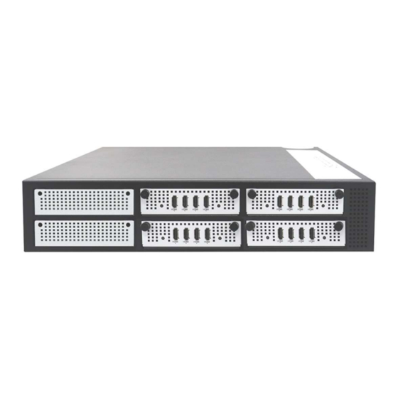
Page 12: Product View
2x GbE ports 4x USB 3.1 ports Power button * Listed from left to right. Rear View * The number of HDMI ports will depend on the number of HDMI module tray installed. This picture is for reference only. SP-63ER User Manual... - Page 13 Backplance Top Cover 2.5” SATA / HDD Backplace Bracket Power Supply Base Cover Bracket CPU Heatsink + Fan 4x HDMI Module Tray 12V Fan 60 x 60 x 15mm 2x 2.5” SATA Bracket I/O Cobbecter Gasket Motherboard SP-63ER User Manual...
-
Page 14: Dimensions
1.6 Dimensions Unit: mm SP-63ER User Manual... -
Page 15: Hardware Installation & Motherboard Information
Chapter 2 Hardware Installation & Motherboard Information The information provided in this chapter includes: Installations Wall Mounting Bracket Rack Mounting Ears Top Cover SSD Storage Graphics Card Memory Mini-PCIe & M.2 Cards ... -
Page 16: Installation / Replacement
To install or replace internal parts or external accessories, follow the instructions in the next pages. 2.1.1 Wall Mounting Bracket Use the eight (8) screws shown below to install/ remove the wall mounting bracket. The screw holes are located at the bottom of the system. SP-63ER User Manual... -
Page 17: Rack Mounting Ears
Hardware Configuration 2.1.2 Rack Mounting Ears Use the ten (10) screws shown below to install/ remove the rack mounting ears. SP-63ER User Manual... -
Page 18: Top Cover
2.1.3 Top Cover To remove the top cover, remove the eight (8) screws shown below. The top cover has to be removed when installing/replacing internal parts such as the SSD storage or graphics card. SP-63ER User Manual... -
Page 19: Ssd Storage
Hardware Configuration 2.1.4 SSD Storage To replace or install the SSD storage, remove the top cover as shown in the previous page and then remove the two (2) screws holding the SSD storage kit. SP-63ER User Manual... -
Page 20: Graphics Card
2.1.5 Graphics Card To replace or install the graphics card, remove the top cover as shown in the previous page and then remove the four (4) screws holding the graphics card kit as shown below. SP-63ER User Manual... -
Page 21: Memory
Hardware Configuration 2.1.6 Memory The MBD63E motherboard housed in the SP-63ER supports two DDR4 memory sockets situated right beside the processor. To install the memory modules, locate the memory slot on the board and perform the following steps: 1. Align the key of the memory module with that on the memory slot and insert the module slantwise. -
Page 22: Setting The Jumpers
2.2 Setting the Jumpers Set up and configure your SP-63ER by using jumpers for various settings and features according to your needs and applications. Contact your supplier if you have doubts about the best configuration. 1.3.1 How to Set Jumpers Jumpers are short-length conductors consisting of several metal pins with a non-conductive base mounted on the circuit board. -
Page 23: Jumper & Connector Locations On Motherboard
2.4.1 JP1: Clear CMOS Function Pin closed Normal (Default) Clear CMOS 2.4.2 JP2: ME Contents Function Pin closed Normal (Default) Clear ME Contents 2.4.3 JP3: Flash Descriptor Security Override (Factory use only) Function Disabled Open (Default) Pin 1-2 Closed Enabled SP-63ER User Manual... -
Page 24: Sw1 / J1 : Atx Power On Switch
2.4.4 JP6: AT/ATX Mode Selection Function Pin closed 2.4.5 JP7: MXM GPU Selection Function Pin closed NVIDIA 2080 / NVIDIA 1080 (default) 2.4.6 SW1 / J1 : ATX Power ON Switch Signal Name Pin # Pin# Function Power BTN- Power BTN+ SP-63ER User Manual... -
Page 25: J2: M.2 B-Key / Sim Card Slot
Hardware Configuration 2.4.7 J2: M.2 B-key / SIM card slot *Supports PCIe (1x), USB 2.0 and 3.0) default Sierra EM7455 2.4.8 CN5 : SIM card SOCKET from J2 M.2 B-key SP-63ER User Manual... -
Page 26: J3: M.2 E-Key
2.4.9 J3: M.2 E-key 2.4.10 J4: Digital I/O Connector (DF11-10S-PA66H) Signal Name Pin # Pin# Function Ground +5V(1A) OUT3 OUT1 OUT2 OUT0 SP-63ER User Manual... -
Page 27: J5: 80 Port
Hardware Configuration 2.4.11 J5: 80 Port 2.4.12 J7: For Debug Use 2.4.13 J8: Reset Button Signal Name Pin # Pin# Function Reset BTN- Reset BTN+ 2.4.14 J9: For SPI Debug Tools Pin Header SP-63ER User Manual... -
Page 28: J10 / J11: Ddr4 So-Dimm Slots
2.4.15 J10 / J11: DDR4 SO-DIMM Slots 2.4.16 J12 : ISMART MCU Program Header SP-63ER User Manual... -
Page 29: J13 : Atx Connector
Hardware Configuration 2.4.17 J13 : ATX Connector 2.4.18 ATX_12V_2X1: ATX 12V Power Connector * This connector supplies the CPU operating voltage. Signal Name Pin # Pin# Function Ground +12V Ground +12V Ground +12V Ground +12V SP-63ER User Manual... -
Page 30: J14: Mini Pci-E Socket
2.4.19 J14: Mini PCI-E Socket 2.4.20 CN7: SIM Card Socket *Signal from J14 MINI PCI-E 2.4.21 J15: MXM SRC Power (YIMTEX_576MWA2*03STR) Signal Name Pin # Pin# Function Ground +12V Ground +12V Ground +12V SP-63ER User Manual... -
Page 31: J16 : Usb3.1 Connectors
Hardware Configuration 2.4.22 J16 : USB3.1 Connectors (PINREX_52X-40-20GU52) Signal Name Pin # Pin# Function VCC(900mA) P1_SSRX- VCC(900mA) P1_SSRX+ P2_SSRX- P2_SSRX+ P1_SSTX- P1_SSTX+ P2_SSTX- P2_SSTX+ P1_U2_D- P1_U2_D+ P2_U2_D- P2_U2_D+ SP-63ER User Manual... -
Page 32: J17 : Usb 2.0 Connector
2.4.23 J17 : USB 2.0 Connector (DF11-8S-PA66H) Signal Name Pin # Pin# Function Vcc(0.5A) Ground Ground Vcc(0.5A) 2.4.24 CN6: MXM Socket SP-63ER User Manual... -
Page 33: Cn8, Cn9: Sata Connectors
Hardware Configuration 2.4.25 CN8, CN9: SATA Connectors 2.4.26 CPU_FAN1: CPU Fan Power Connector Signal Name Pin # Pin# Function Ground Rotation detection +12V Control SP-63ER User Manual... -
Page 34: Cn1: Com1 Rs-232/422/485 Ports
RTS, Request to send TXD, Transmit data CTS, Clear to send DTR, Data terminal ready RI, Ring indicator Ground 2.4.28 CN2 / CN3: GbE LAN Port and Dual USB 3.1 Ports *CN3: Intel WGI219LM / CN2: Intel WGI211AT SP-63ER User Manual... -
Page 35: Cn4: Audio Connector
Hardware Configuration 2.4.29 CN4: Audio Connector 2.4.30 LED1: Power LED / HDD LED *Green for Power LED / Red for HDD LED SP-63ER User Manual... -
Page 36: Chapter 3 Driver Installation
Chapter 3 Driver Installation The information provided in this chapter includes: Intel® Chipset Software Installation Utility HD Audio Driver LAN Driver Intel® Management Engine Drivers Installation Intel® Serial IO Drivers Installation ... -
Page 37: Introduction
INF files for Plug & Play function for the chipset components. Follow the instructions below to complete the installation. 1. Insert the disk enclosed in the package with the board. Click Intel on the left pane and then Intel(R) Coffeelake Chipset Drivers on the right pane. SP-63ER User Manual... - Page 38 Chipset Device Software appears, click Next to continue. 4. Accept the software license agreement and proceed with the installation process. 5. On the Readme File Information screen, click Install. 6. After the installation, click Finish to complete the setup process. SP-63ER User Manual...
-
Page 39: Nvidia Graphics Driver Installation
Driver Installation 3.3 NVIDIA Graphics Driver Installation 1. Extract the NVIDIA Graphics Driver files. After extraction, the installation shall check the system compatibility. SP-63ER User Manual... - Page 40 2. After System Check is done, click AGREE AND CONTINUE. 3. On the next screen, choose Express (Recommended) and click NEXT. SP-63ER User Manual...
- Page 41 Driver Installation 4. When the NVIDIA Installer has finished, click RESTART NOW. SP-63ER User Manual...
-
Page 42: Realtek High Definition Audio Driver Installation
3.4 Realtek High Definition Audio Driver Installation 1. Insert the disk enclosed in the package with the board. Click Intel on the left pane and then Intel(R) Coffelake Chipset Drivers on the right pane. 2. Click Realtek High Definition Audio Driver. SP-63ER User Manual... - Page 43 3. On the Welcome screen of the InstallShield Wizard, click Next. The InstallShield Wizard will install Realtek High Definition Audio Driver on your computer. 4. When the driver is completely installed, restart the computer for changes to take effect. SP-63ER User Manual...
-
Page 44: Lan Driver Installation
3.5 LAN Driver Installation 1. Insert the disk enclosed in the package with the board. Click LAN Card on the left pane and then Intel LAN Controller Drivers on the right pane. SP-63ER User Manual... - Page 45 5. On the Setup Options screen, select the desired features you want installed. Then click Next to continue. 6. On the Ready to Install the Program screen, click Next to start. 7. When the Install wizard has completed the installation, click Finish. SP-63ER User Manual...
-
Page 46: Intel Management Engine Components Drivers Installation
Management Engine Components Drivers Installation 1. Insert the disk enclosed in the package with the board. Click Intel on the left pane and then Intel(R) Coffelake Chipset Drivers on the right pane. 2. Click Intel(R) ME 12.x Drivers. SP-63ER User Manual... - Page 47 3. When the Welcome screen appears, click Next. 4. Accept the license agreement and click Next. 5. On the next screen, click Next to accept the destination folder. Installatoin shall begin. 6. After Intel Management Engine Components have been installed, click Finish. SP-63ER User Manual...
-
Page 48: Chapter 4 Bios Setup
Chapter 4 BIOS Setup This chapter describes the different settings available in the AMI BIOS that comes with the board. The topics covered in this chapter are as follows: Main Settings Advanced Settings Chipset Settings Security Settings ... -
Page 49: Introduction
These defaults have been carefully chosen by both AMI and your system manufacturer to provide the absolute maximum performance and reliability. Changing the defaults could make the system unstable and crash in some cases. SP-63ER User Manual... -
Page 50: Main Settings
System Time Use the <Tab> key to switch between the data elements. 4.4 Advanced Settings This section allows you to configure, improve your system and allows you to set up some system features according to your preference. SP-63ER User Manual... - Page 51 Hyper-Threading Enabled or Disabled Enable/Disable AES (Advanced Encryption Standard) Enables / Disables utilization of additional Intel Trusted Execution hardware capabilities provided by Intel(R) Trusted Technology Execution Technology. Changes require a full power cycle to take effect. SP-63ER User Manual...
- Page 52 Enabling will expose the CPPC V2 Technology interface to allow for hardware to allow for hardware controlled P states. Enables/Disables processor Turbo Mode (requires Turbo Mode Intel Speed Step or Intel Speed Shift to be available and enabled). SP-63ER User Manual...
- Page 53 BIOS Setup 4.4.3 PCH-FW Configuration BIOS Setting Description When disable, ME will be put into ME Temporarily ME State Disabled Mode. SP-63ER User Manual...
- Page 54 TPM 1.2 will restrict support to TPM 1.2 devices. TPM 2.0 will restrict support to TPM 2.0 devices. Device Select Auto will support both with the default set to TPM 2.0 devices. If not found, TPM 1.2 devices will be enumerated. SP-63ER User Manual...
- Page 55 Enables / Disables system ability to hibernate Enable Hibernation (OS/S4 Sleep State). This option may not be effective with some operating systems. Selects the highest ACPI sleep state the system ACPI Sleep State will enter when the SUSPEND button is pressed. SP-63ER User Manual...
- Page 56 For example, if setting up a schedule from Wednesday 5 p.m. to Thursday 2 a.m., configure two schedule slots. But if setting up a schedule from 3 p.m to 5 p.m. on Wednesday, configure only a schedule slot. SP-63ER User Manual...
- Page 57 F81966 Super IO Configuration BIOS Setting Description Serial Port 1 Configuration Sets parameters of Serial Port 1 (COMA). Serial Port Enable / Disable the serial port. Change Settings Select an optimal setting for the Super IO device. SP-63ER User Manual...
- Page 58 PC health status. Options: Disabled 70C / 158F 75C / 167F CPU Shutdown Temperature 80C / 176 F 85C / 185F 90C / 194F 95C / 203F Options: Auto M.2 B Key Selection Sata / USB 3.0 PCIe SP-63ER User Manual...
- Page 59 The maximum time the device will take before it properly reports itself to the Host Controller. Device power-up delay “Auto” uses default value for a Root port it is 100ms. But for a Hub port, the delay is taken from Hub descriptor. SP-63ER User Manual...
- Page 60 4.4.10 CSM Configuration BIOS Setting Description CSM Support Enables/Disables CSM Support. Network Controls the execution of UEFI and Legacy PXE OpROM. 4.4.11 NVMe Configuration SP-63ER User Manual...
- Page 61 PXE boot wait time PXE boot. Use either +/- or numeric keys to set the value. Number of times the presence of media will be Media detect count chcked. Use either +/- or numeric keys to set the value. SP-63ER User Manual...
-
Page 62: Chipset Settings
4.5 Chipset Settings BIOS Setting Description System Agent (SA) Configuration System Agent (SA) parameters PCH-IO Configuration PCH parameters SP-63ER User Manual... - Page 63 BIOS Setup 4.5.1 System Agent (SA) Configuration BIOS Setting Description Graphics Configuration Configures the graphics settings. VT-d Checks if VT-d function on MCH is supported. SP-63ER User Manual...
- Page 64 2048 MB aperture. To use this feature, disable CSM support. DVMT Pre- 0M, 32M, 64M, 4M, 8M, 12M, 16M, 20M, 24M, 28M, 32M/F7, Alocated 36M, 40M, 44M, 48M, 52M, 56M, 60M DVMT Total Gfx 128M, 256M, MAX SP-63ER User Manual...
- Page 65 4.5.2 PCH-IO Configuration BIOS Setting Description SATA and RST Configures SATA devices. Configuration PCH LAN Enables / Disables the onboard NIC. Controller Wake on LAN Enables / Disables the integrated LAN to wake up the system. Enable SP-63ER User Manual...
- Page 66 Enables / Disables the SATA device. Controller(s) SATA Mode Determines how SATA controller(s) operate. Options: Selection AHCI / Intel RST Premium Serial ATA Enables / Disables serial ports. Ports SATA Ports Hot Enables / Disables SATA Ports HotPlug. Plug SP-63ER User Manual...
-
Page 67: Security Settings
BIOS Setup 4.6 Security Settings BIOS Setting Description Administrator Sets an administrator password for the setup utility. Password User Password Sets a user password. Secure Boot Configures Secure Boot. SP-63ER User Manual... - Page 68 Restore Factory Forces system to user mode. Install factory default Keys Secure Boot key databases. Enables expert users to modify Secure Boot Policy Management variables without full authentication. SP-63ER User Manual...
-
Page 69: Boot Settings
65535(0xFFFF) means indefinite waiting. Bootup NumLock Selects the keyboard NumLock state. State Quiet Boot Enables / Disables Quiet Boot option. Boot mode select Selects a Boot mode, Legacy / UEFI. Boot Option Sets the system boot order. Priorities SP-63ER User Manual... -
Page 70: Save & Exit Settings
Restores / Loads defaults values for all the setup Restore Defaults options. Save as User Defaults Saves the changes done so far as User Defaults. Restore User Defaults Restores the user defaults to all the setup options. SP-63ER User Manual... -
Page 71: Appendix
Appendix This section provides the mapping addresses of peripheral devices and the sample code of watchdog timer configuration. I/O Port Address Map Interrupt Request Lines (IRQ) -
Page 72: I/O Port Address Map
Programmable interrupt controller 0x000000B0-0x000000B1 Programmable interrupt controller 0x000000B4-0x000000B5 Programmable interrupt controller 0x000000B8-0x000000B9 Programmable interrupt controller 0x000000BC-0x000000BD Programmable interrupt controller 0x000004D0-0x000004D1 Programmable interrupt controller 0x00001854-0x00001857 Motherboard resources 0x000003F8-0x000003FF Communications Port (COM1) 0x000002F8-0x000002FF Communications Port (COM2) 0x00001800-0x000018FE Motherboard resources SP-63ER User Manual... - Page 73 NVIDIA GeForce GTX 1080 0x000003B0-0x000003BB Intel(R) PCIe Controller (x16) - 1901 0x000003C0-0x000003DF NVIDIA GeForce GTX 1080 0x000003C0-0x000003DF Intel(R) PCIe Controller (x16) - 1901 0x00003000-0x00003FFF Intel(R) PCI Express Root Port #12 - A333 0x0000EFA0-0x0000EFBF Intel(R) SMBus - A323 SP-63ER User Manual...
-
Page 74: Interrupt Request Lines (Irq)
IRQ 4294967283-290 Intel(R) I211 Gigabit Network Connection IRQ 4294967291 Intel(R) USB 3.1 eXtensible Host Controller - 1.10 (Microsoft) IRQ 4294967292 NVIDIA GeForce GTX 1080 IRQ 4294967293 Intel(R) Ethernet Connection (7) I219-LM IRQ 4294967294 Standard SATA AHCI Controller SP-63ER User Manual... -
Page 75: Umcc Quick Guide
UMCC C from the menu to control the panel. After modifying SP-63ER resolution with the AP, modify the Windows display setting again. Since the Windows "Apply" default value is 15 seconds, the user needs to set the Windows display setting to more than 15 seconds. - Page 76 Setting: User can set the display durating in UMCC setting window. Apply: Click "Apply" to confirm the setting Device information: This shows Software version, device No. and device ID. Device Setting Sync: User can write multi-device parameter SP-63ER User Manual...
- Page 77 Horizon Polarity: Set the H SYNC Polarity Vertical Polarity: Set the V SYNC Polarity. Color Depth: Set display color depth Audio Support: Set HDMI Audio On or off EDID Version: Set the EDID version. DP Port: Change the screen resolution by resolution table. SP-63ER User Manual...
- Page 78 Vertical rate: Define the parameter for vertical rate. Horizon Display Parameter: Set the parameter for Horizon rate. Vertical Display Parameter: Set the parameter for Vertical rate. SP-63ER User Manual...
- Page 79 Appendix SP-63ER User Manual...
Need help?
Do you have a question about the SP-63ER and is the answer not in the manual?
Questions and answers