Table of Contents
Advertisement
Quick Links
Advertisement
Table of Contents

Related Manuals for IBASE Technology AMS300-1


Summary of Contents for IBASE Technology AMS300-1
- Page 1 AMS300-1 Compact Expandable Fanless System User’s Manual Version 1.0 (July 2019)
- Page 2 No part of this publication may be reproduced, copied, stored in a retrieval system, translated into any language or transmitted in any form or by any means, electronic, mechanical, photocopying, or otherwise, without the prior written consent of IBASE Technology, Inc. (hereinafter referred to as “IBASE”).
-
Page 3: Compliance
CE conformity declaration may no longer apply. AMS300-1 has been tested and found to comply with the limits for a Class B device pursuant to Part 15 of the FCC Rules. These limits are designed to provide reasonable protection against harmful interference in a residential installation. -
Page 4: Important Safety Information
Important Safety Information Carefully read the precautions before using the device. Environmental conditions: • Lay the device horizontally on a stable and solid surface. • Make sure you leave plenty of space around the device for ventilation. • Use this product in environments with ambient temperatures -10˚C ~ 50˚C. •... -
Page 5: Technical Support & Services
Software in use (such as OS and application software, including the version numbers) 3. If repair service is required, please log in to the RMA system of the website or contact your distributor or sales representative for assistance. AMS300-1 User Manual... -
Page 6: Table Of Contents
General Information ..............1 Introduction ..................... 2 Features ....................2 Packing List .................... 3 Optional Accessories ................4 Specifications ..................5 Overview – AMS300-1 ................7 Dimensions – AMS300-1 ................ 9 Chapter 2 Hardware Configuration ............10 Hardware Installations ................11 2.1.1 Memory Installation / Replacement ......... - Page 7 USB Configuration ..............56 Chipset Settings ..................58 Security Settings ................... 61 Boot Settings..................62 Save & Exit Settings................63 Appendix ...................... 64 I/O Port Address Map ................65 Interrupt Request Lines (IRQ) ............... 68 Watchdog Timer Configuration .............. 70 AMS300-1 User Manual...
- Page 8 This page is intentionally left blank. viii AMS300-1User Manual...
-
Page 9: Chapter 1 General Information
Chapter 1 General Information The information provided in this chapter includes: • Features • Packing List • Optional Accessories • Specifications • Overview • Dimensions... -
Page 10: Introduction
1.1 Introduction The AMS300-1 is an embedded computing system designed for thin clients, smart industrial automation or controller, and retail equipment applications. It ® is a compact and fanless platform powered by an Intel Gen. Core™ i7 / i5 / i3 desktop processor and features iSMART technology that allows power on/off auto-scheduling and provides energy savings with reliable operation. -
Page 11: Packing List
AMS300-1 • AMS300-1 • Terminal Block for DC-In Power Adapter (3 pins) • Terminal Block for Remote Power Button (2 pins) • Wall Mount Kit • Round Head Screw (for Wall Mount Kit) AMS300-1 User Manual... -
Page 12: Optional Accessories
• DC-In power adapter • Power cord • WiFi antenna kit • Side mount bracket • DIN rail bracket • Cable kit for 2 SSD assembly (including 4 screws, and a SATA cable) AMS300-1 User Manual... -
Page 13: Specifications
Desktop mount / Wall mount (wall mount kit included) Mounting • DIN rail mount (optional) Dimensions 275 x 70 x 140 mm (W x H x D) Weight 2.7 kg Certificate CE / LVD / FCC Class B AMS300-1 User Manual... - Page 14 All specifications are subject to change without prior notice. IBD190 with IBLD170 for 3rd LAN use *IBD190: Mini PCI-E LAN card with Intel I211-AT Ethernet controller, single port; used with IBLD170 RJ45 card (IBLD170 includes a transformer, RJ45, and LCD112 cable.) AMS300-1 User Manual...
-
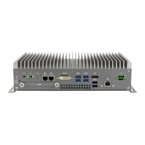
Page 15: Overview - Ams300-1
General Information 1.6 Overview – AMS300-1 Front View Rear View Name Name LED Indicator DisplayPort (CN10) (from top to bottom: S1*, E1*, SSD, Power) GbE LAN port (3rd LAN, Power Button (SW1) via IBD190 / IBLD170) Terminal Block for Remote... - Page 16 Wall Mount DIN Rail Mount Side Mount AMS300-1 User Manual...
-
Page 17: Dimensions - Ams300-1
General Information 1.7 Dimensions – AMS300-1 Unit: mm AMS300-1 User Manual... -
Page 18: Chapter 2 Hardware Configuration
Chapter 2 Hardware Configuration The information provided in this chapter includes: • Essential installations before you begin • Information and locations of connectors... -
Page 19: Hardware Installations
3. Hold the memory module and align the key of the module with that on the memory slot. 4. Gently push the module in an upright position until the ejector tabs of the memory slot close to hold the module in place when the module touches the bottom of the slot. AMS300-1 User Manual... -
Page 20: Ssd Installation
2.1.2 SSD Installation To install or replace the SSD, follow the instructions below for installation. This is illustrated by the example of AMS300-1. SSD: 1. Release 2 screws to pull out the SSD tray. 2. Put your 2.5” SSD into the tray and secure it with the supplied 4 screws... - Page 21 SSD onto the bracket, secure it with 4 screws as pointed by arrows below. 4. Then secure the bracket and replace the device cover. Note: The screws and cables for the 2 SSD can be optionally purchased from IBASE. AMS300-1 User Manual...
-
Page 22: Wifi / 3G / 4G Antenna Installation
1. Thread and fasten the hex nut and the 2. Apply adhesive around here. washer. Then install the antenna. Info: The diameter of the nut is around 6.35 mm (0.25”-36UNC). AMS300-1 User Manual... -
Page 23: Mounting Installation
Fasteners are not supplied in the product package. You will need to prepare the fasteners. Choose fasteners that are rated either Medium Duty or Heavy Duty. To assure proper fastener selection and installation, follow the fastener manufacturer’s recommendations. AMS300-1 User Manual... - Page 24 2.1.6.1. Wall-Mounting Installation 1. Attach the mounting brackets and secure them with the supplied 4 screws. 2. Prepare at least 4 screws (M3) to install the device on wall . AMS300-1 User Manual...
- Page 25 Hardware Configuration 2.1.6.2. Side-Mounting Installation (Optional) 1. Attach the mounting bracket to your product, and secure with the supplied 4 screws. 2. Prepare at least 4 screws (M3) to install the device on wall . AMS300-1 User Manual...
- Page 26 Secure with 4 screws for a rotatable bracket. 2. Hook the DIN rail mounting bracket over the top of the DIN rail, and then press the lower section of the bracket towards the DIN rail to clip the bracket onto it. AMS300-1 User Manual...
-
Page 27: Dc-In & Power Button Connectors
Hardware Configuration 2.1.5 DC-In & Power Button Connectors • DC-In Power Connector (3-pin terminal block) Assigment Case Ground Power Ground • Remote Control Connector (2-pin terminal block) Assigment Power BTN Ground AMS300-1 User Manual... -
Page 28: Setting The Jumpers
When two pins of a jumper are encased in a jumper cap, this jumper is closed, i.e. turned On. When a jumper cap is removed from two jumper pins, this jumper is open, i.e. turned Off. AMS300-1 User Manual... -
Page 29: Jumper & Connector Locations On Motherboard
Hardware Configuration 2.3 Jumper & Connector Locations on Motherboard Motherboard: MB300-1 AMS300-1 User Manual... -
Page 30: Jumpers Quick Reference
2.4 Jumpers Quick Reference Function Jumper Page Clear CMOS Data JBAT1 Clear RTC Content JBAT2 CPU dGfx Bifurcation Selection JP1, JP2 Factory Use Only 2.4.1 Clear CMOS Data (JBAT1) Function Illustration Normal (default) Closed Clear CMOS Closed AMS300-1 User Manual... -
Page 31: Clear Rtc Content (Jbat2)
Hardware Configuration 2.4.2 Clear RTC Content (JBAT2) Function Illustration Normal Open (default) Clear RTC Closed AMS300-1 User Manual... -
Page 32: Cpu Dgfx Bifurcation Selection (Jp1, Jp2)
JP1: Open 1 x PCIe (x16) (default) JP2: Open JP1: Closed 2 x PCIe (x8) JP2: Open JP1: Open RSVD JP2: Closed JP1: Closed 1 x PCIe (x8), 1 x PCIe (x4), 1 x PCIe (x4) JP2: Closed AMS300-1 User Manual... -
Page 33: Connectors Quick Reference
Remarks: The page numbers refers to the pages where the connectors could be found, whether it be their pin definitions or to indicate where they are located. Page 7 refers to the rear I/O picture page, while page 21 to the motherboard drawing. AMS300-1 User Manual... -
Page 34: Sata Power Connector (J5, J6)
2.5.1 SATA Power Connector (J5, J6) Assignment Assignment Ground Ground 2.5.2 Digital Connector (J4) Assignment Assignment Ground VCC5 OUT3 OUT1 OUT2 OUT0 AMS300-1 User Manual... -
Page 35: System Fan Power Connector (Sys_Fan1)
Hardware Configuration 2.5.3 System Fan Power Connector (SYS_FAN1) Assignment Ground Rotation detection AMS300-1 User Manual... -
Page 36: Chapter 3 Driver Installation
Chapter 3 Driver Installation The information provided in this chapter includes: • ® Intel Chipset Software Installation Utility • HD Audio Driver Installation • LAN Driver Installation • ® Intel Management Engine Driver Installation • USB 3.1 Driver Installation... -
Page 37: Introduction
1. Go to the download page of the product. Copy the compressed drivers file to your computer. Double click the file to decompress it. Run “CDGuide” to go to the main drivers page as shown. Click Intel and then Intel(R) Skylake-U/Kabylake-U Chipset Drivers. 2. Click Intel(R) Chipset Software Installation Utility. AMS300-1 User Manual... - Page 38 ® 3. When the Welcome screen to the Intel Chipset Device Software appears, click Next to continue. 4. Accept the software license agreement and proceed with the installation process. AMS300-1 User Manual...
- Page 39 Driver Installation 5. On the Readme File Information screen, click Install and then Next for installation. 6. The driver has been completely installed. You are suggested to restart the computer for changes to take effect. AMS300-1 User Manual...
-
Page 40: Graphics Driver Installation
3.3 Graphics Driver Installation 1. Click Intel and then Intel(R) Skylake-U/Kabylake-U Chipset Drivers. 2. Click Intel(R) HD Graphics Driver. 3. When the Welcome screen appears, click Next to continue. AMS300-1 User Manual... - Page 41 4. Click Yes to agree with the license agreement and continue the installation. 5. Read the Readme File Information and then click Next. 6. Choose a destination folder for installation. 7. The driver has been completely installed. Click Finish and restart the computer for changes to take effect. AMS300-1 User Manual...
-
Page 42: Hd Audio Driver Installation
2. Click Realtek High Definition Audio Driver. 3. On the Welcome screen of the InstallShield Wizard, click Next for installation. 4. The driver has been completely installed. You are suggested to restart the computer for changes to take effect. AMS300-1 User Manual... -
Page 43: Lan Driver Installation
1. Click LAN Card and then Intel(R) Skylake-U/Kabylake-U Chipset Drivers 2. Click Intel(R) PRO LAN Network Drivers.. 3. When the Welcome screen appears, click Next to continue. 4. Accept the license agreement and click Next to continue. AMS300-1 User Manual... - Page 44 5. Tick the checkbox for Drivers to select the related drivers and click Next. 6. When the wizard is ready for installation, click Install. 7. The driver has been completely installed. You are suggested to restart the computer for changes to take effect. AMS300-1 User Manual...
-
Page 45: Intel Management Engine Driver Installation
3. When the Welcome screen appears, click Next to continue. 4. Accept the licence agreement and click Next to continue. 5. The driver has been completely installed. You are suggested to restart the computer for changes to take effect. AMS300-1 User Manual... -
Page 46: Usb 3.1 Driver Installation
3.7 USB 3.1 Driver Installation 1. Click Intel and then Intel(R) Skylake-U/Kabylake-U Chipset Drivers. 2. Click ASMedia USB 3.1 Drivers. 3. When the Welcome screen appears, click Next to continue. AMS300-1 User Manual... - Page 47 Driver Installation 4. Accept the licence agreement and click Next to continue. 5. The driver has been completely installed. You are suggested to restart the computer for changes to take effect. AMS300-1 User Manual...
-
Page 48: Chapter 4 Bios Setup
Chapter 4 BIOS Setup This chapter describes the different settings available in the AMI BIOS that comes with the board. The topics covered in this chapter are as follows: • Main Settings • Advanced Settings • Chipset Settings • Security Settings •... -
Page 49: Introduction
These defaults have been carefully chosen by both AMI and your system manufacturer to provide the absolute maximum performance and reliability. Changing the defaults could make the system unstable and crash in some cases. AMS300-1 User Manual... -
Page 50: Main Settings
4.3 Main Settings BIOS Setting Description System Date Sets the date. Use the <Tab> key to switch between the date elements. System Time Set the time. Use the <Tab> key to switch between the time elements. AMS300-1 User Manual... -
Page 51: Advanced Settings
Sets up schedules for power management. F81846 Super IO Displays super IO chip parameters. Configuration F81846 Hardware Shows super IO monitor hardware status. Monitor CSM Configuration Enables / Disables option ROM execution settings, etc. USB Configuration Displays USB configuration parameters. AMS300-1 User Manual... -
Page 52: Cpu Configuration
Options: All, 1, 2, 3 Enables / Disables AES (Advanced Encryption Standard). Intel Trusted Execution Enables / Disables unilization of additional Technology hardware capabilities provided by Intel(R) Trusted Execution Technology. Changes require a full power cycle to take effect. AMS300-1 User Manual... -
Page 53: Power & Performance
CPPC v2 interface to allow for hardware controlled P-states. Turbo Mode Enables / Disables processor Turbo Mode (requires EMTTM enabled too). “Auto” means enabled unless max turbo ratio is bigger than 16-SKL A0 W/A. AMS300-1 User Manual... -
Page 54: Pch-Fw Configuration
PCH-FW Configuration BIOS Setting Description AMT BIOS Features When disabled AMT BIOS features are no longer supported and user is no longer able to access MEBx Setup. Note: This option does not disable manageability features in FW. AMS300-1 User Manual... -
Page 55: Acpi Settings
Enables / Disables the system ability to hibernate (OS/S4 Sleep State). This option may not be effective with some OS. ACPI Sleep State Selects a ACPI sleep state for the system to enter. Options: Suspend Disabled, S3 (Suspend to RAM) AMS300-1 User Manual... -
Page 56: Ismart Controller
For example, if setting up a schedule from Wednesday 5 p.m. to Thursday 2 a.m., configure two schedule slots. But if setting up a schedule from 3 p.m to 5 p.m. on Wednesday, configure only a schedule slot. AMS300-1 User Manual... -
Page 57: F81846 Super Io Configuration
BIOS Setup 4.4.6 F81846 Super IO Configuration BIOS Setting Description Serial Port Configuration Sets Parameters of Serial Ports. You can enable / disable the serial port and select an optimal settings for the Super IO device. AMS300-1 User Manual... - Page 58 IO = 2E8h; IRQ = 3, 4, 5, 6, 7, 9, 10, 11, 12 F81846 Serial Port1 F81846 serial port 1 loop back / RS232 / Mode Select RS422 / RS485 model select. RS422/RS485 Enables / Disables RS422/RS485 termination. Termination AMS300-1 User Manual...
- Page 59 IO = 2F8h; IRQ = 3, 4, 5, 6, 7, 9, 10, 11, 12 • IO = 3E8h; IRQ = 3, 4, 5, 6, 7, 9, 10, 11, 12 • IO = 2E8h; IRQ = 3, 4, 5, 6, 7, 9, 10, 11, 12 AMS300-1 User Manual...
- Page 60 IO = 2E8h; IRQ = 3, 4, 5, 6, 7, 9, 10, 11, 12 • IO = 2F0h; IRQ = 3, 4, 5, 6, 7, 9, 10, 11, 12 • IO = 2E0h; IRQ = 3, 4, 5, 6, 7, 9, 10, 11, 12 AMS300-1 User Manual...
- Page 61 IO = 2E8h; IRQ = 3, 4, 5, 6, 7, 9, 10, 11, 12 • IO = 2F0h; IRQ = 3, 4, 5, 6, 7, 9, 10, 11, 12 • IO = 2E0h; IRQ = 3, 4, 5, 6, 7, 9, 10, 11, 12 AMS300-1 User Manual...
-
Page 62: F81846 Hardware Monitor
The values are read-only as monitored by the system and showing the PC health status CPU Shutdown This field enables or disables the Shutdown Temperature Temperature Options: Disabled (default),. 70 °C, 75 °C, 80 °C, 85 °C, 90 °C, 95 °C AMS300-1 User Manual... -
Page 63: Csm Configuration
BIOS Setup 4.4.8 CSM Configuration BIOS Setting Description Network Controls the execution of UEFI and Legacy PXE OpROM. AMS300-1 User Manual... -
Page 64: Usb Configuration
Sets the time-out value 1, 5, 10 or 20 sec(s) for Control, Bulk, and Interrupt transfers. Device reset time-out Sets the seconds (10, 20, 30, 40 secs) of delaying execution of start unit command to USB mass storage device. AMS300-1 User Manual... - Page 65 The maximum time the device will take before it properly reports itself to the Host Controller. Auto uses default value. For a Root port, it is 100 ms. For a Hub port, the delay is taken from Hub descriptor. AMS300-1 User Manual...
-
Page 66: Chipset Settings
4.5 Chipset Settings BIOS Setting Description System Agent (SA) System Agent (SA) parameters Configuration VT-d Enables / Disables VT-d capability. AMS300-1 User Manual... - Page 67 BIOS Setup 4.5.1 PCH-IO Configuration BIOS Setting Description SATA and RST SATA device options and settings Configuration PCH LAN Controller Enables / Disables onboard NIC. Wake on LAN Enable Enables / Disables integrated LAN to wake the system. AMS300-1 User Manual...
- Page 68 BIOS Setting Description SATA Controller(s) Enables / Disables the Serial ATA. SATA Mode Selection Determines how SATA controller(s) works. AHCI Mode or Intel RST Premium. Serial ATA Port 0~2 Enables / Disables Serial Port 0 ~ 2. AMS300-1 User Manual...
-
Page 69: Security Settings
BIOS Setup 4.6 Security Settings BIOS Setting Description Administrator Password Sets an administrator password for the setup utility. User Password Sets a user password. AMS300-1 User Manual... -
Page 70: Boot Settings
Has no effect for BBS boot options. Boot mode select Selects a Boot mode, Legacy / UEFI. Boot Option Priorities Sets the system boot order priorities for hard disk, CD/DVD, USB, Network. AMS300-1 User Manual... -
Page 71: Save & Exit Settings
Restore Defaults Restores / Loads defaults values for all the setup options. Save as User Defaults Saves the changes done so far as user defaults. Restore User Defaults Restores the user defaults to all the setup options. AMS300-1 User Manual... -
Page 72: Appendix
Appendix This section provides the mapping addresses of peripheral devices and the sample code of watchdog timer configuration. • I/O Port Address Map • Interrupt Request Lines (IRQ) • Watchdog Timer Configuration... -
Page 73: I/O Port Address Map
0x0000FFFF-0x0000FFFF Motherboard resources 0x00001800-0x000018FE Motherboard resources 0x0000164E-0x0000164F Motherboard resources 0x00000020-0x00000021 Programmable interrupt controller 0x00000024-0x00000025 Programmable interrupt controller 0x00000028-0x00000029 Programmable interrupt controller 0x0000002C-0x0000002D Programmable interrupt controller 0x00000030-0x00000031 Programmable interrupt controller 0x00000034-0x00000035 Programmable interrupt controller 0x00000038-0x00000039 Programmable interrupt controller AMS300-1 User Manual... - Page 74 Motherboard resources 0x00000000-0x00000CF7 PCI Express Root Complex 0x00000D00-0x0000FFFF PCI Express Root Complex 0x0000F0A0-0x0000F0A7 Intel(R) Active Management Technology - SOL (COM5) 0x0000F000-0x0000F03F Intel(R) HD Graphics 630 0x000003B0-0x000003BB Intel(R) HD Graphics 630 0x000003C0-0x000003DF Intel(R) HD Graphics 630 0x0000FF00-0x0000FFFE Motherboard resources AMS300-1 User Manual...
- Page 75 Appendix Address Device Description 0x0000F040-0x0000F05F Intel(R) 100 Series/C230 Series Chipset Family SMBus - A123 0x00000060-0x00000060 Standard PS/2 Keyboard 0x00000064-0x00000064 Standard PS/2 Keyboard AMS300-1 User Manual...
-
Page 76: Interrupt Request Lines (Irq)
IRQ 4294967288 Intel(R) I211 Gigabit Network Connection IRQ 4294967289 Intel(R) I211 Gigabit Network Connection IRQ 4294967290 Intel(R) USB 3.0 eXtensible Host Controller - 1.0 (Microsoft) IRQ 4294967291 Intel(R) HD Graphics 630 IRQ 4294967292 Intel(R) Ethernet Connection (2) I219-LM AMS300-1 User Manual... - Page 77 Appendix Level Function IRQ 4294967293 Standard SATA AHCI Controller IRQ 4294967294 Intel(R) 100 Series/C230 Series Chipset Family PCI Express Root Port #6 - A115 AMS300-1 User Manual...
-
Page 78: Watchdog Timer Configuration
**endptr; char SIO; printf("Fintek 81866 watch dog program\n"); SIO = Init_F81866(); if (SIO == 0) printf("Can not detect Fintek 81866, program abort.\n"); return(1); }//if (SIO == 0) if (argc != 2) printf(" Parameter incorrect!!\n"); return (1); AMS300-1 User Manual... - Page 79 //--------------------------------------------------------------------------- void DisableWDT(void) unsigned char bBuf; Set_F81866_LD(0x07); //switch to logic device 7 bBuf = Get_F81866_Reg(0xFA); bBuf &= ~0x01; Set_F81866_Reg(0xFA, bBuf); //disable WDTO output bBuf = Get_F81866_Reg(0xF5); bBuf &= ~0x20; bBuf |= 0x40; Set_F81866_Reg(0xF5, bBuf); //disable WDT //--------------------------------------------------------------------------- AMS300-1 User Manual...
- Page 80 (ucDid == 0x07) //Fintek 81866 goto Init_Finish; } F81866_BASE = 0x00; result = F81866_BASE; Init_Finish: return (result); //--------------------------------------------------------------------------- void Unlock_F81866 (void) outportb(F81866_INDEX_PORT, F81866_UNLOCK); outportb(F81866_INDEX_PORT, F81866_UNLOCK); //--------------------------------------------------------------------------- void Lock_F81866 (void) outportb(F81866_INDEX_PORT, F81866_LOCK); //--------------------------------------------------------------------------- void Set_F81866_LD( unsigned char LD) Unlock_F81866(); AMS300-1 User Manual...
- Page 81 #define F81866_DATA_PORT (F81866_BASE+1) //--------------------------------------------------------------------------- #define F81866_REG_LD 0x07 //--------------------------------------------------------------------------- #define F81866_UNLOCK 0x87 #define F81866_LOCK 0xAA //--------------------------------------------------------------------------- unsigned int Init_F81866(void); void Set_F81866_LD( unsigned char); void Set_F81866_Reg( unsigned char, unsigned char); unsigned char Get_F81866_Reg( unsigned char); //--------------------------------------------------------------------------- #endif // F81866_H AMS300-1 User Manual...
Need help?
Do you have a question about the AMS300-1 and is the answer not in the manual?
Questions and answers