ATEN CE750 - USB KVM Extender Quick Start Guide
- Application manual (6 pages) ,
- User manual (34 pages)
Advertisement
Package Contents
The CE750 package consists of:
1 CE750L USB KVM Extender (Local Unit)
1 CE750R USB KVM Extender (Remote Unit)
1 USB KVM Cable (1.8 m)
2 Power Adapters
1 Rack Mount Kit
2 Grounding Wires
1 User Manual
1 Quick Start Guide
Requirements
Consoles
- A VGA, SVGA, SXGA, UXGA, or multisync monitor capable of the highest resolution that you will be using on any computer in the installation
Note: If you connect a DDC type monitor to the Local Unit, the monitor that connects to the Remote Unit must be able to support the highest video resolution that the DDC monitor can provide - A USB keyboard
- A USB mouse
Computers
The following equipment must be installed on each computer that is to be connected to the system:
- A VGA, SVGA, SXGA, UXGA, or multisync card.
- USB host controller and Type A USB port.
Cables
- For optimal signal integrity, and to simplify the layout, we strongly recommend that you use the high quality custom USB KVM Cable that is provided with this package.
- Cat 5e cable is the minimum required to connect the Local and Remote CE750 Units. Cable of a lower standard will result in degrading of the video signal. For best performance, we strongly recommend Cat 5e cable.
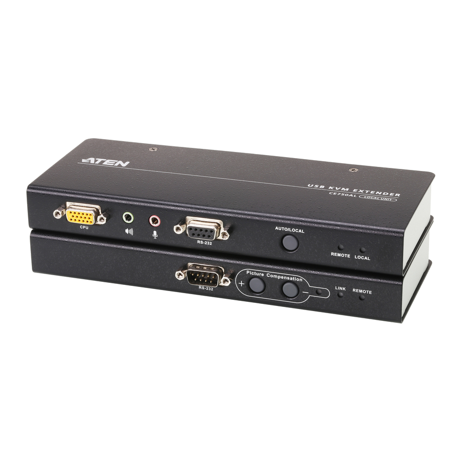
Hardware Review
CE750L (Local Unit) Front View

- KVM Port Section
- RS-232 Serial Port
- Operating Mode Pushbutton
- LEDs
CE750R (Remote Unit) Front View

- RS-232 Serial Port
- Picture Compensation Pushbuttons
- Picture Compensation LED
- LEDs
CE750L / CE750R Rear View, Side View

- Power Jack
- USB Keyboard / Mouse ports
- Audio Ports
- Remote I/O
- Monitor Port
- Grounding Terminal
Hardware Installation
Rack Mounting

For convenience and flexibility, the CE750L and CE750R can be mounted on system racks. To rack mount a unit do the following:
- Using the screws provided in the Rack Mount Kit, screw the mounting bracket into the top or bottom of the unit as show in the diagram below:
- Screw the bracket into any convenient location on the rack.
Note: These screws are not provided. We recommend that you use M5 x 12 Phillips Type I cross, recessed type screws.
Setting Up

Setting up the USB KVM Extender system is simply a matter of plugging in the cables. Make sure that all the equipment to be connected up is powered Off. Refer to the installation diagram on the following page and do the following:
- Plug the cables from the local console devices (mouse, keyboard, monitor, microphone, speakers) into their ports on the Console section on the rear of the Local Unit (CE750L). Each port is marked with an appropriate icon to indicate itself.
- Plug the appropriate connectors on the USB KVM cable supplied with this unit into their ports on the CPU section on the front of the Local Unit (CE750L).
- Plug the connectors on the other end of the USB KVM cable into the appropriate ports on the local computer. Each connector is marked with an appropriate icon to indicate which it is.
Note: If you are combining the CE750 with a KVM switch, the other end of the USB KVM cable plugs into the appropriate ports on the KVM switch. - For control of serial devices, connect the RS-232 serial port on the local unit to a serial port on the local computer.
- Plug either end of the Cat 5e cable into the CE750L's Remote I/O port. Plug the other end of the Cat 5e cable into the I/O port of the Remote Unit (CE750R).
- Plug one of the power adapters (supplied with this package) into an AC source; plug the adapter's power cable into the CE750L's Power Jack.
- Plug the cables from the remote console devices (mouse, keyboard, monitor, speakers. microphone), into their ports on the Console side of the CE750R.
- Plug the second power adapter (supplied with this package) into an AC source; plug the adapter's power cable into the CE750R's Power Jack.
Operation
Operating Modes
The CE750 USB KVM Extender has three operating modes: Local, Auto, and Remote, as described in the table below:
| Mode | Description |
| Local | Only the local console has KVM access. The remote console's keyboard and mouse input is disabled. |
| Auto | Both the local and remote consoles can have KVM access, but not at the same time. The console without access has to wait until the console with access stops inputting data before it can gain access. |
| Remote | The remote console has KVM access. Remote mode can only occur when the pushbutton on the CE750L is set to Auto and the local console is idle. |
Note: The default operating mode is Auto.
Online Registration
International:
North America:
- http://www.aten-usa.com/product_registration (ATEN TECH)
- http://support.aten.com (ATEN NJ)
Technical Phone Support
International:
- 886-2-86926959
North America:
- 1-888-999-ATEN (ATEN TECH)
- 1-732-356-1703 (ATEN NJ)
© Copyright 2008 ATEN® International Co., Ltd.
ATEN and the ATEN logo are trademarks of ATEN International Co., Ltd. All rights reserved. All other trademarks are the property of their respective owners.
This product is RoHS compliant.
Manual Part No. PAPE-1223-430G Printing Date: 08/2008


Documents / Resources
References
Download manual
Here you can download full pdf version of manual, it may contain additional safety instructions, warranty information, FCC rules, etc.
Advertisement


Need help?
Do you have a question about the CE750 and is the answer not in the manual?
Questions and answers