Table of Contents
Advertisement
Quick Links
Advertisement
Table of Contents

Subscribe to Our Youtube Channel
Related Manuals for ATEN CE750A


Summary of Contents for ATEN CE750A
- Page 1 USB KVM Extender CE750A User Manual www.aten.com...
-
Page 2: Emc Information
CE750A User Manual EMC Information FEDERAL COMMUNICATIONS COMMISSION INTERFERENCE STATEMENT: This equipment has been tested and found to comply with the limits for a Class A digital device, pursuant to Part 15 of the FCC Rules. These limits are designed to provide reasonable protection against harmful interference when the equipment is operated in a commercial environment. -
Page 3: User Information
CE750A User Manual User Information Online Registration Be sure to register your product at our online support center: International http://support.aten.com North America http://www.aten-usa.com/product_registration Telephone Support For telephone support, call this number: 886-2-8692-6959 International 86-400-810-0-810 China 81-3-5615-5811 Japan Korea 82-2-467-6789 North America... -
Page 4: Package Contents
© Copyright 2019 ATEN® International Co., Ltd. Manual Part No. PAPE-0297-AT4G Manual Date: 2019-01-07 ATEN and the ATEN logo are registered trademarks of ATEN International Co., Ltd. All rights reserved. All other brand names and trademarks are the registered property of their respective owners. -
Page 5: Table Of Contents
CE750A User Manual Contents EMC Information ..........ii RoHS. - Page 6 CE750A User Manual Appendix Safety Instructions ......... . 21 General .
-
Page 7: About This Manual
An overview of the information found in the manual is provided below. Chapter 1, Introduction, introduces you to the CE750A system. Its purpose, features and benefits are presented, and its front and back panel components are described. -
Page 8: Product Information
For information about all ATEN products and how they can help you connect without limits, visit ATEN on the Web or contact an ATEN Authorized Reseller. Visit ATEN on the Web for a list of locations and telephone numbers: International http://www.aten.com... -
Page 9: Introduction
Because it allows access to a computer system from a remote console, the CE750A is perfect for use in any type of installation where you need to place the console where it is conveniently accessible, but you want the system equipment to reside in a safe location –... -
Page 10: Features
Supports Wide Screen formats* Note: The EDID data for a widescreen is sent from the local video output port. For widescreen modes and displays connect the monitor to the local video output port or use an ATEN EDID emulator. -
Page 11: Requirements
Cat 5e cable is the minimum required to connect the Local and Remote CE750A Units. Cable of a lower standard will result in degrading of the video signal. For best performance, we strongly recommend Cat 5e cable. -
Page 12: Operating Systems
CE750A User Manual Operating Systems Supported operating systems are shown in the table, below: Version Windows 2000 and higher Linux RedHat 7.1 and higher SuSE 9.0 and higher Mandriva (Mandrake) 9.0 and higher UNIX FreeBSD 4.2 and higher Novell Netware... -
Page 13: Components
CE750AL (Local Unit) Front View Component Description KVM Port Section If you are combining the CE750A with a KVM switch, the custom KVM cable set that links to the respective ports on the Console section of the switch plugs into these ports. -
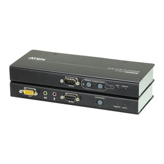
Page 14: Ce750Ar (Remote Unit) Front View
CE750A User Manual CE750AR (Remote Unit) Front View Component Description RS-232 Serial Port RS-232 serial devices – such as touchscreens or barcode scanners – plug into this port. Picture Compensation These pushbuttons adjust the video quality of the Pushbuttons remote console. See Picture Compensation, page 19 for details. -
Page 15: Ce750Al / Ce750Ar Rear View
Chapter 1. Introduction CE750AL / CE750AR Rear View Side View Component Description Power Jack The cable from the DC Power adapter connects here. Audio Ports These mini stereo ports are for the speakers (green) and microphone (pink). Remote I/O The Cat 5e cable that connects the Remote and Local Units plugs in here. - Page 16 CE750A User Manual This Page Intentionally Left Blank...
-
Page 17: Hardware Setup
Chapter 2 Hardware Setup 1. Important safety information regarding the placement of this device is provided on page 21. Please review it before proceeding. 2. Make sure that the power to all devices connected to the installation are turned off. You must unplug the power cords of any computers that have the Keyboard Power On function. - Page 18 CE750A User Manual 2. Screw the bracket into any convenient location on the rack. Phillips Type I cross M5 x 12 (Recommended) Note: These screws are not provided. We recommend that you use M5 x 12 Phillips Type I cross, recessed type screws.
-
Page 19: Installation
Chapter 2. Hardware Setup Installation Grounding To prevent damage to your installation it is important that all devices are properly grounded. 1. Use two grounding wires to ground both units by connecting one end of the wire to the grounding terminal, and the other end of the wire to a suitable grounded object. - Page 20 CE750A User Manual 3. For increased grounding protection, use STP (shielded twisted pair) cable to connect the Local and Remote Units. There are two methods that can be used: a) In addition to the eight paired wires, STP cable also contains a grounding wire.
-
Page 21: Setting Up
Each connector is marked with an appropriate icon to indicate which it is. Note: If you are combining the CE750A with a KVM switch, the other end of the custom KVM cable set plugs into the appropriate ports on the KVM switch. -
Page 22: Installation Diagrams
CE750A User Manual Installation Diagrams CE750AL / CE750AR Rear View CE750AL Cat 5e cable CE750AR... -
Page 23: Ce750Al Front View
Chapter 2. Hardware Setup CE750AL Front View Local PC Custom KVM cable set... - Page 24 CE750A User Manual This Page Intentionally Left Blank...
-
Page 25: Operation
Chapter 3 Operation Operating Modes The CE750A USB KVM Extender has three operating modes: Local, Auto, and Remote, as described in the table below: Mode Description Local Only the local console has KVM access. The remote console’s keyboard, video, and mouse input is disabled. -
Page 26: Mode Selection
Mode Selection The Operating Mode Pushbutton, located on the CE750AL’s front panel, controls the operating mode of the CE750A USB KVM Extender system. Pressing the switch toggles through Local and Auto operating modes. Note: Remote mode cannot be selected. The remote console can get control only when the Operating Mode Pushbutton on the CE750AL is toggled to Auto and the local console is idle. -
Page 27: Picture Compensation
Manual adjustment To fine tune the video signal, use the Picture Compensation pushbuttons on the front panel of the remote CE750A to increase and/or decrease the compensation. The picture compensation LED flashes as the system adjusts its video gain, and lights steadily when the adjustment is complete... -
Page 28: Led Display
CE750A User Manual LED Display The CE750A Local and Remote Units have front panel LEDs to indicate their operating status, as shown in the tables, below: CE750AL (Local Unit) Operating Mode Local Auto Local Lights to indicate Lights when the local console is active (the Remote... -
Page 29: Appendix
Appendix Safety Instructions General Read all of these instructions. Save them for future reference. Follow all warnings and instructions marked on the device. Do not place the device on any unstable surface (cart, stand, table, etc.). If the device falls, serious damage will result. Do not use the device near water. - Page 30 CE750A User Manual If an extension cord is used with this device make sure that the total of the ampere ratings of all products used on this cord does not exceed the extension cord ampere rating. Make sure that the total of all products plugged into the wall outlet does not exceed 15 amperes.
-
Page 31: Rack Mounting
Appendix Rack Mounting Before working on the rack, make sure that the stabilizers are secured to the rack, extended to the floor, and that the full weight of the rack rests on the floor. Install front and side stabilizers on a single rack or front stabilizers for joined multiple racks before working on the rack. -
Page 32: Technical Support
CE750A User Manual Technical Support International For online technical support – including troubleshooting, documentation, and software updates: http://support.aten.com For telephone support, see Telephone Support, page iii. North America Email Support support@aten-usa.com Online Troubleshooting http://www.aten-usa.com/support Technical Documentation Support Software Updates Telephone Support... -
Page 33: Specifications
Appendix Specifications Function CE750AL CE750AR Connectors Console Keyboard 1 x USB Type A Female (White) Ports Video 1 x HDB-15 Female (Blue) Mouse 1 x USB Type A Female (White) Speakers 1 x Mini Stereo Jack Female (Green) Mic. 1 x Mini Stereo Jack Female (Pink) RS-232 1 x DB-9 Female 1 x DB-9 Male (Black) -
Page 34: Troubleshooting
CE750A User Manual Troubleshooting Overview Operation problems can be due to a variety of causes. The first step in solving them is to make sure that all cables are securely attached and seated completely in their sockets. Problem Action No video Make sure that all cables are securely plugged into their sockets. -
Page 35: Limited Warranty
ATEN will provide a repair service, without charge, during the Warranty Period. If a product is detective, ATEN will, at its discretion, have the option to (1) repair said product with new or repaired components, or (2) replace the entire product with an identical product or with a similar product which fulfills the same function as the defective product. - Page 36 CE750A User Manual...
Need help?
Do you have a question about the CE750A and is the answer not in the manual?
Questions and answers