ATEN Altusen KE9950 / KE9952 Quick Start Guide
- User manual (470 pages) ,
- User manual (324 pages) ,
- User manual (466 pages)
Advertisement
Package Contents
1 KE9950T or KE9952T 4K DisplayPort KVM over IP Extender (Transmitter)
1 KE9950R or KE9952R 4K DisplayPort KVM over IP Extender (Receiver)
1 DisplayPort Cable (KE9950T / KE9952T only)
1 USB 2.0 Type-A to Type-B Cable (KE9950T / KE9952T only)
2 Power Adapters (KE9950T / KE9950R only)
2 Power Cords (KE9950T / KE9950R only)
1 Foot Pad Set (4 pcs.) for KE9950T or KE9952T
1 Mounting Kit for KE9950T or KE9952T
1 User Instructions
Hardware Review
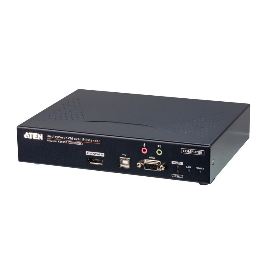
KE9950T / KE9952T Front View

- Audio Ports
- KVM Ports
- RS-232 Port
- Remote / Local LED
- LAN LED
- Power LED
KE9950T / KE9952T Rear View

- Grounding Terminal
- Reset (Recessed Button)
- Audio Ports
- Power Jack
- Function Switch
- RS-232 Port
- USB Ports (Console)
- LAN Port
- SFP Slot
- DisplayPort Output (Console)
- Power Jack (KE9950T only)*
KE9950R / KE9952R Front View

- Power LED
- LAN LED
- Local LED
- Remote LED
- Graphics Pushbutton
- OSD Pushbutton
- Video Pushbutton
- USB Port (Peripheral)
KE9950R / KE9952R Rear View

- Grounding Terminal
- Reset (Recessed Button)
- Audio Ports
- USB Port (Peripheral)
- Power Jack
- Function Switch
- RS-232 Port
- USB Ports (Console)
- LAN Port
- SFP Slot
- DisplayPort Output (Console)
- Power Jack (KE9950R only)*
* This port is not available on KE9952T / KE9952R.
Hardware Installation
Use the screws provided with the mounting kit to screw the mounting bracket to the bottom of the unit (Refer to the drawings shown below). For rack mounting, screw the mounting bracket to any convenient location on the rack. For wall mounting, use the mounting bracket's center screw hole to mount the unit on a wall.

Note: Rack screws are not provided to mount the unit. We recommend that you use M5 x 12 Phillips type I cross screws.
Point-to-Point Installation

- (Optional) Use the grounding wire to connect the extender's grounding terminal to a suitable grounded object.
- On the transmitter side, plug the mouse, keyboard, DisplayPort monitor, and serial devices into the ports on the Console section of the KE9950T / KE9952T.
- Connect the DisplayPort cable and the USB 2.0 Type-A to Type-B cable provided with this package into the KVM Ports on the front of the KE9950T / KE9952T.
- Connect the other end of the DisplayPort cable and the USB 2.0 Type-A to Type-B cable respectively into the video and USB ports on the computer.
- For control of serial devices, connect the RS-232 port on the front of the transmitter to a serial port on the computer.
- Connect a Cat 5e/6 cable to the KE9950T / KE9952T's LAN port.
- On the receiver side, plug the mouse, keyboard, DisplayPort monitor, and serial devices into the ports on the Console section of the KE9950R / KE9952R.
- Connect the other end of the Cat 5e/6 cable to the KE9950R / KE9952R's LAN port.
- Instead of connecting through the LAN ports, you can choose to connect the KE9950 / KE9952 through the SFP slots. To do so, plug SFP modules into the transmitter and receiver's SFP slots, then connect each end of Gigabit Ethernet (GbE) optical fi ber between the SFP modules.**
- Plug the power adapters into AC sources with the power cords and plug the other ends into the transmitter and receiver's power jacks respectively. The KE9952 supports Power over Ethernet (PoE) where power can be supplied through a PoE network switch instead of using a power adapter.
- (Optional) For power redundancy, plug the second power adapters into AC sources with the power cords and plug the other ends into the transmitter and receiver's second power jacks respectively.***
- Power on the computer.
**The SFP module 2A-136G / 2A-137G is sold separately. Contact your ATEN dealer for product information.
*** The second power jacks are available on KE9950T and KE9950R only. The second power adapter with the power cord is sold separately. Contact your ATEN dealer for product information. Power redundancy for KE9952T and KE9952R can be achieved with the PoE function.
OSD Options
Both the transmitter and receiver units are confi gured from the OSD menu on the receiver. To invoke the OSD, either press the front panel OSD pushbutton (receiver only), or tap the [Scroll Lock] key twice. The password to enter the OSD confi guration screens is: password. The username / password to enter the System Login page in Matrix Mode is: administrator / password.
To exit the OSD, press the [Esc] key; click Logout or Back to Video from the OSD menu; or return to the OSD Main menu and press the front panel OSD pushbutton.
Support and Documentation Notice
All information, documentation, fi rmware, software utilities, and specifi cations contained in this package are subject to change without prior notifi cation by the manufacturer.
To reduce the environmental impact of our products, ATEN documentation and software can be found online at
http://www.aten.com/download/
Technical Support
www.aten.com/support
Scan for more information


Documents / Resources
References
Download manual
Here you can download full pdf version of manual, it may contain additional safety instructions, warranty information, FCC rules, etc.
Advertisement


Need help?
Do you have a question about the Altusen KE9950 and is the answer not in the manual?
Questions and answers