Table of Contents
Advertisement
Advertisement
Table of Contents

Related Manuals for ATEN CE790


Summary of Contents for ATEN CE790
- Page 1 Digital KVM Extender CE790 User Manual www.aten.com...
-
Page 2: Rohs
CE790 User Manual FCC Information This is an FCC Class A product. In a domestic environment this product may cause radio interference in which case the user may be required to take adequate measures. This equipment has been tested and found to comply with the limits for a Class A digital device, pursuant to Part 15 of the FCC Rules. -
Page 3: User Information
PLEASE VERIFY THAT THE VOLTAGE SETTING IS CORRECT BEFORE USE. This ATEN product is specifically designed and manufactured for the operation and management of computer mainframe and communications equipment used in network management centers. As such, it may not be completely appropriate for those environments and sites where special standards for performance and high reliability are required –... -
Page 4: Package Contents
Manual Part No. PAPE-0310-ATXG F/W Version: v.2.1.204 Manual Date: 2011-01-14 ATEN and the ATEN logo are registered trademarks of ATEN International Co., Ltd. All rights reserved. All other brand names and trademarks are the registered property of their respective owners. -
Page 5: Table Of Contents
CE790 User Manual Contents FCC Information ii RoHS............ii SJ/T 11364-2006. - Page 6 CE790 User Manual CE790T ..........20 CE790R.
-
Page 7: About This Manual
An overview of the information found in the manual is provided below. Chapter 1, Introduction, introduces you to the CE790 system. Its purpose, features and benefits are presented, and its front and back panel components are described. -
Page 8: Conventions
For information about all ATEN products and how they can help you connect without limits, visit ATEN on the Web or contact an ATEN Authorized Reseller. Visit ATEN on the Web for a list of locations and telephone numbers: International http://www.aten.com... -
Page 9: Introduction
The CE790 is also useful for control and security purposes, where you can have the system unit in a secure area at the same time that you put the console in the most convenient location for user access. -
Page 10: Features
Rack mountable Firmware upgradable – via web browser Auto MDIX – automatically detects cable type Note: 1. The CE790 AP and GUI operation instructions can be downloaded from the ATEN website (www.aten.com). 2. RS-232 serial ports support Tx/Rx/CTS/RTS signals only. -
Page 11: Requirements
Chapter 1. Introduction Requirements Consoles A VGA, SVGA, SXGA, UXGA, or multisync monitor capable of the highest resolution that you will be using on any computer in the installation Note: If you connect a DDC type monitor to the Transmitter Unit, the monitor that connects to the Receiver Unit must be able to support the highest video resolution that the DDC monitor can provide A USB keyboard... -
Page 12: Video Resolutions
CE790 User Manual Video Resolutions Supported video resolutions are show in the table, below: Resolution @ Hz Standard 640 x 480p IBM VGA 72, 75 VESA 800 x 600p 56, 60, 72, 75 1024 x 768p 60, 70, 75 VESA... -
Page 13: Components
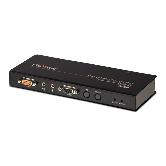
Chapter 1. Introduction Components CE790T (Transmitter) Front View SELECT STATUS POWER Component Description KVM Port Section The USB KVM cable supplied with the CE790T package that links the CE790T to the computer plugs into these ports. See Installation, page 11, for further details. -
Page 14: Ce790R (Receiver) Front View
CE790 User Manual CE790R (Receiver) Front View SELECT POWER STATUS Component Description RS-232 Serial Port RS-232 serial devices – such as touchscreens or barcode scanners – plug into this port. OSD Pushbutton Press this pushbutton to invoke the CE790R’s On Screen Display (OSD). -
Page 15: Ce790T / Ce790R Rear View
Chapter 1. Introduction CE790T / CE790R Rear View Side View Component Description Power Jack The cable from the DC Power adapter connects here. Audio Ports These mini stereo ports are for the speakers (green) and microphone (pink). LAN Port The Cat 5e cable that connects the CE790T and CE790R Units plugs to the TCP/IP LAN plugs in here. - Page 16 CE790 User Manual This Page Intentionally Left Blank...
-
Page 17: Hardware Setup
Chapter 2 Hardware Setup 1. Important safety information regarding the placement of this device is provided on . Please review it before proceeding. 2. Make sure that the power to all devices connected to the installation are turned off. You must unplug the power cords of any computers that have the Keyboard Power On function. - Page 18 CE790 User Manual 2. Screw the bracket into any convenient location on the rack. Note: These screws are not provided. We recommend that you use M5 x 12 Phillips Type I cross, recessed type screws.
-
Page 19: Installation
Chapter 2. Hardware Setup Installation Grounding To prevent damage to your installation it is important that all devices are properly grounded. 1. Use the two grounding wires supplied with this package to ground both units by connecting one end of the wire to the grounding terminal, and the other end of the wire to a suitable grounded object. - Page 20 CE790 User Manual 3. For increased grounding protection, use STP (shielded twisted pair) cable to connect the Local and Remote Units. There are two methods that can be used: a) In addition to the eight paired wires, STP cable also contains a grounding wire.
-
Page 21: Setting Up A Point-To-Point Installation
Each connector is marked with an appropriate icon to indicate which it is. Note: If you are combining the CE790 with a KVM switch, the other end of the USB KVM cable plugs into the appropriate console ports on the KVM switch. -
Page 22: Point-To-Point Installation Diagrams
CE790 User Manual Point-to-Point Installation Diagrams CE790T / CE790R Rear View Cat 5e cable CE790T Cat 5e cable CE790R... -
Page 23: Ce790T Front View
Chapter 2. Hardware Setup CE790T Front View SELECT STATUS POWER Local PC USB KVM cable Note: The serial port on the CE790T connects to the computer; the serial port on the CE790R (not shown) connects to a serial device (optional). -
Page 24: Setting Up A Networked Installation
CE790 User Manual Setting Up a Networked Installation Setting up the CE790 Digital KVM Extender system in a networked configuration allows point-to-point, point-to-multipoint, and multipoint-to- multipoint operation by connecting multiple CE790Ts and CE790Rs over the same TCP/IP LAN. Note: 1. The CE790T/CE790R units are preconfigured with factory-default network settings. - Page 25 Chapter 2. Hardware Setup 7. Next, at the receiver site, plug the cables from the console devices (mouse, keyboard, monitor, speakers. microphone), into their ports on the Console section of the CE790R. 8. Connect the other end of the Cat 5e cable to the CE790R's LAN port (located on the rear of the unit).
-
Page 26: Networked Installation Diagram
CE790 User Manual Networked Installation Diagram CE790T / CE790R Rear View Cat 5e cable CE790T IGMP- enabled TCP/IP LAN Cat 5e cable CE790R Note: See p. 15 for the CE790T front view installation diagram. -
Page 27: Osd Operation
OSD Operation Overview This section provides a description of the procedures involved in the configuration and operation of your CE790 installation, including how to use the On Screen Display (OSD). LED Display Both the CE790T transmitter and CE790R receiver units have front panel... -
Page 28: Osd Main Screens
CE790 User Manual OSD Main Screens When you invoke the OSD, screens similar to the ones below appears: CE790T CE790R... -
Page 29: Osd Navigation
Chapter 3. OSD Operation OSD Navigation Action Method Using the CE790T / Use the OSD pushbutton on the front of the unit to cycle CE790R Pushbuttons the OSD highlight bar through the available options. When your option is highlighted, press the Select pushbutton. -
Page 30: Osd Functions
CE790 User Manual OSD Functions Video Quality (CE790T only) The CE790 allows you to transmit low/normal/high/ultra high video quality images. To set the video quality, do the following: 1. Invoke the OSD (See Invoking the OSD, page 19). 2. Select Video Quality from the main menu. The sub-menu appears. -
Page 31: Destination (Ce790T Only)
Chapter 3. OSD Operation Destination (CE790T only) This option allows you to connect the CE790T transmitter(s) to one or many CE790R receiver units (i.e.. the destination) in point-to-point and point-to- multipoint configurations over the TCP/IP LAN. Note: 1. To set the network topology, see [insert cross ref] 2. -
Page 32: Source (Ce790R Only)
CE790 User Manual Source (CE790R only) This option allows you to connect the CE790R receiver(s) to a CE790T transmitter unit (i.e.. the source) in the point-to-point configurations over the TCP/IP LAN that you have already set up on the CE790T. -
Page 33: Configuration
LAN, setting the duration, and setting the OSD invocation hotkeys. Note: 1. The CE790T/CE790R units are preconfigured with factory-default network settings. If you install only one CE790 Digital KVM Extender system (that is, one CE790T and one CE790R), you do not need to change these default network settings. -
Page 34: Return
RETURN pushbutton on the front of the unit. The OSD disappears and your computer desktop screen will be displayed. Default IP Addresses The preconfigured factory-default IP addresses for the CE790 units are as follows: CE790T – 192.168.168.15 CE790R – 192.168.168.16... -
Page 35: Osd Function Summary
Chapter 3. OSD Operation OSD Function Summary CE790T Setting Function Allows you to set the video compression ratio. VIDEO QUALITY Note: The default setting is NORMAL. SPEAKER Allows you to turn the audio on/off. Note: The default setting is Allows you to turn the microphone on/off. Note: The default setting is DESTINATION Allows you to connect to or disconnect from a CE790R, connect to... - Page 36 CE790 User Manual This Page Intentionally Left Blank...
-
Page 37: The Firmware Upgrade Utility
To prepare for the firmware upgrade, do the following: 1. Go to our Internet support site and download the Firmware Upgrade Package for your device (CE790). 2. After the file has been downloaded, reconfigure your computer’s IP address so that it resides on the same network as the CE790T/CE790R. -
Page 38: Starting The Upgrade
CE790 User Manual Starting the Upgrade To upgrade your firmware: 1. Open a web browser and key in the following address: Upgrading the CE790T – http://192.168.168.15/upg.htm Upgrading the CE790R – http://192.168.168.16/upg.htm The Firmware Upgrade screen appears: 2. Click Browse to find the Firmware Upgrade file you have just downloaded. -
Page 39: Appendix
Appendix Safety Instructions General Read all of these instructions. Save them for future reference. Follow all warnings and instructions marked on the device. Do not place the device on any unstable surface (cart, stand, table, etc.). If the device falls, serious damage will result. Do not use the device near water. - Page 40 CE790 User Manual If an extension cord is used with this device make sure that the total of the ampere ratings of all products used on this cord does not exceed the extension cord ampere rating. Make sure that the total of all products plugged into the wall outlet does not exceed 15 amperes.
-
Page 41: Rack Mounting
Appendix Rack Mounting Before working on the rack, make sure that the stabilizers are secured to the rack, extended to the floor, and that the full weight of the rack rests on the floor. Install front and side stabilizers on a single rack or front stabilizers for joined multiple racks before working on the rack. -
Page 42: Technical Support
CE790 User Manual Technical Support Technical support is available both by email and online (with a browser over the web): International For online technical support – including troubleshooting, documentation, and software updates: http://support.aten.com For telephone support, see Telephone Support, page iii. -
Page 43: Specifications
Appendix Specifications Function CE790T CE790R Connectors Console Keyboard 1 x USB Type A Female (White) Ports Video 1 x HDB-15 Female (Blue) Mouse 1 x USB Type A Female (White) Speaker 1 x Mini Stereo Jack Female (Green) Mic. 1 x Mini Stereo Jack Female (Pink) RS-232 1 x DB-9 Female 1 x DB-9 Male (Black) -
Page 44: Troubleshooting
CE790 User Manual Troubleshooting Overview Operation problems can be due to a variety of causes. The first step in solving them is to make sure that all cables are securely attached and seated completely in their sockets. Problem Action No video Make sure that all cables are securely plugged into their sockets.
Need help?
Do you have a question about the CE790 and is the answer not in the manual?
Questions and answers