ATEN Altusen KE8900ST, Altusen KE8900SR - Extender Quick Start Guide
- User manual (324 pages) ,
- User manual (466 pages)
Advertisement
Package Contents
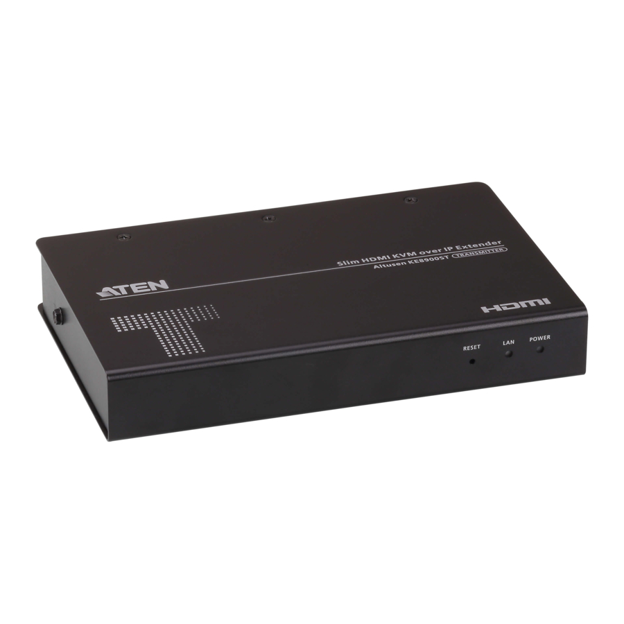
KE8900ST
1 Slim HDMI KVM over IP Extender (Transmitter)
1 USB HDMI KVM Cable
1 Power Adapter
1 Mounting Kit
1 HDMI Lockpro*
1 User Instructions
KE8900SR
1 Slim HDMI KVM over IP Extender (Receiver)
1 Power Adapter
1 Mounting Kit
1 HDMI Lockpro*
1 User Instructions
* Please refer to http://www.aten.com/global/en/products/professional-audiovideo/accessories/2x-ea12/#.WPROpmd-XIU for the installation of HDMI Lockpro
Hardware Review
KE8900ST Front View

- Reset (Recessed Button)
- LAN LED
- Power LED
KE8900ST Rear View

- LAN Port
- RS-232 Port
- USB Type-B Port
- HDMI Port
- 3-Pole Terminal Bloc (Power Input)
- Power Jack
KE8900ST / KE8900SR Side View

- Grounding Terminal
KE8900SR Front View

- USB Peripheral Ports
- USB Ports (Console)
- Reset (Recessed Button)
- LAN LED
- Power LED
KE8900SR Rear View

- LAN Port
- RS-232 Port
- HDMI Port
- Power Jack
Hardware Installation

Rack Mounting

- Use the screws provided with the mounting kit to screw the mounting bracket to the bottom of the unit (Refer to the drawings shown above).
- Screw the mounting bracket to any convenient location on the rack.
Note: The KE8900ST / KE8900SR can be installed in the ATEN VE-RMK 1U Extender Rack Mount Kit. To purchase this kit contact your local dealer.
Wall Mounting

- Use the screws provided with the mounting kit to screw the mounting bracket to the bottom of the unit (Refer to the drawings shown above).
- Use the mounting bracket's center screw hole to mount the unit on a wall.
Point-to-Point Installation
For a direct unit to unit installation, do the following

- (Optional) Connect the grounding terminals of KE8900ST and KE8900SR to a suitable grounded object using grounding wires.
- Connect the USB HDMI KVM Cable provided with this package between a computer and the KE8900ST. Please use the USB Type-B end of the USB HDMI KVM Cable for the KE8900ST as it has a USB Type-B port.
- Connect a Cat 5e/6 cable between the LAN ports of KE8900ST and KE8900SR.
- Connect a USB mouse/keyboard to the front panel of the KE8900SR and HDMI monitor to the rear panel of the KE8900SR.
- Plug the power adapters into power sockets; then plug the other ends respectively into KE8900ST and KE8900SR's power jacks. For KE8900ST, you can choose to use the terminal block for power input and connect the power wires according to the icon.*
- (Optional) For control of serial devices, connect the RS-232 serial port on the KE8900ST to a serial port on the computer.
- Power on the computer.
Setting up a LAN Installation
Setting up the units on a network allows point-to-point, point-to-multipoint, and multipoint-to-multipoint computer to console operation by connecting multiple KE Series devices on the same TCP/IP LAN. To set up a LAN installation, simply connect the Cat 5e/6 cable (in step 3) to the network instead of directly between two KE Series devices.
* OSD Options *
The On-Screen Display is a keyboard and mouse driven menu-based application to handle control and configuration of KE operations. Both the transmitter and receiver units are confi gured from the OSD menu on the receiver. Once the transmitter and receiver units have discovered each other (over a network or direct connection) you can use the receiver's OSD menu to maintain confi guration and control of the setup. To invoke the OSD, tap the [Scroll Lock] key twice. Password information is provided under OSD Options. To exit the OSD, press the [Esc] key; click Logout or Back to Video from the OSD menu; or return to the OSD Main menu. When the OSD menu exits, the computer's screen will appear.
| No. | Item | Description |
| 1 | User Station | Select this radio button, enter the password, and click Configure to enter the User Station configuration screen. |
| 2 | Transmitter | Select this radio button, enter the password, and click Configure to enter the Transmitter configuration screen. |
| 3 | User Preferences | Select this radio button, enter the password, and click Configure to enter the User Preferences configuration screen. |
| 4 | Configure | After entering a password, click this button to enter the selected configuration screen. |
Note: The password to enter the OSD confi guration screens is: password. The username / password to enter the System Login page in Matrix Mode is: administrator / password.
Support and Documentation Notice
All information, documentation, fi rmware, software utilities, and specifi cations contained in this package are subject to change without prior notifi cation by the manufacturer. To reduce the environmental impact of our products, ATEN documentation and software can be found online at http://www.aten.com/download/
Technical Support
www.aten.com/support
Scan for more information

© Copyright 2018 ATEN ® International Co., Ltd.
ATEN and the ATEN logo are trademarks of ATEN International Co., Ltd. All rights reserved. All other trademarks are the property of their respective owners.
This product is RoHS compliant.


Documents / Resources
References
Download manual
Here you can download full pdf version of manual, it may contain additional safety instructions, warranty information, FCC rules, etc.
Download ATEN Altusen KE8900ST, Altusen KE8900SR - Extender Quick Start Guide
Advertisement


Need help?
Do you have a question about the Altusen KE8900ST and is the answer not in the manual?
Questions and answers