Table of Contents
Advertisement
Quick Links
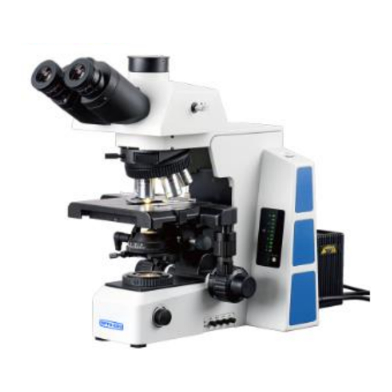
A12.0910
Research Scientific Laboratory Microscope,
Semi-APO, Upgrade BF+DF+PL+PH+FL+DIC
Instruction Manual
This instruction manual is for the operation guide, troubleshooting and
maintenance to the A12.0910 series biological microscope. Please study this
manual thoroughly before operating, and keep it with the instrument. The
manufacturer reserves the rights to the modifications by technology
development. On the basis of operation ensured, technical specifications
may be subject to changes without notice.
Advertisement
Table of Contents

Related Manuals for OPTO-EDU A12.0910


Summary of Contents for OPTO-EDU A12.0910
- Page 1 Instruction Manual This instruction manual is for the operation guide, troubleshooting and maintenance to the A12.0910 series biological microscope. Please study this manual thoroughly before operating, and keep it with the instrument. The manufacturer reserves the rights to the modifications by technology development.
-
Page 2: Table Of Contents
4. Assembling and Operation of Fluorescence Illuminator ............17 4-1 Assemblage Steps ......................17 4-2 Operation ......................... 21 5. Troubleshooting .......................... 26 5-1 Solutions of A12.0910 Series Biological Microscope Problem ........26 5-2 Solutions of Mercury Bulb Fluorescent Device Problem ..........28... -
Page 3: Before Use
Before Use A12.0910 1. Operation Notice 1. As the microscope is a high precision instrument, always operate it with care, and avoid physical shake during the operation. 2. Do not expose the microscope in the sun directly, either not in the high temperature, damp, dust or acute shake. -
Page 4: Components
1. Components A12.0910 A12.0910 Series Biological Microscope Components Inner Y-axis Moving Hexagon Light Path Knob Selecting Pole Spanner Objective Trinocular head Body Mechanical Stage Light Condenser Source Group X-axis Moving Knob Illuminator Light Tension Switch Lever Reset Button Voltage Adjustment... - Page 5 A12.0910 Dust Cover Nosepiece Objective Condenser up-down knob Coarse Adjusting Fine Coarse Limit Ring Focusing Focusing Knob Knob...
- Page 6 A12.0910 A12.0910FL Series Biological Fluorescence Microscope Components Aperture Diaphragm Lens Focusing Knob Adjusting Pole Vertical Vertical centering Field Diaphragm Fluorescence Screw Adjusting Pole Illuminator Horizontal centering Screw Trinocular head Flashboard knob Blinkers Board XY Body Diaphragm Centering Screw Power Supply Box...
- Page 7 A12.0910 ND Filter Slot...
-
Page 8: Assembling
Following is the Assembling Scheme, and the numbers denote the assembling order. ★ Before assembling, make sure there is no dust, dirt or other matters to affect the assembly. Assemble carefully and do not scrap any part or touch the glass surface. 1. A12.0910 Series Biological Microscope Assembling Scheme... - Page 9 A12.0910 2. A12.0910 Series Biological Fluorescence Microscope Assembling Scheme...
-
Page 10: Assembling Steps
A12.0910 2-2 Assembling Steps 2-2-1 Assemble and Replace the Halogen Bulb (1) Loose lock-screw ① completely by M4 spanner , then take off the cover group. (See Fig. 1) (2) Open the bulb lock piece②, and take the bulb③ with clean glove or soft tissue, insert the bulb pins④... - Page 11 A12.0910 2-2-4 Assemble the Condenser (1) Rotate the coarse focusing knob① to raise stage to the highest. (See Fig. 5) (2) Rotate the condenser up-down knob② to lower the condenser bracket to the lowest. (3) Loosen the condenser lock-screw③ fully.
- Page 12 A12.0910 ★When replacing the objective, rotate the nosepiece until it sounds “ka-da”, to make sure the objective is in the center of the light path. 2-2-8 Assemble the Eyepiece (1) Take down the cover of eyepiece tube① (See Fig. (2) Insert the eyepiece into the eyepiece tube, until touch the bottom.
-
Page 13: Operation
3. Operation A12.0910 3-1 Set Illumination (1) Put through the power and turn on the main power switch to“—” (see Fig. 11). (2) Adjust the light adjustment knob ④ until the illumination is comfortable for observation. Rotate the light adjustment knob clockwise to raise the voltage and brightness. -
Page 14: Select The Light Path
A12.0910 3-3 Select the Light Path For trinocular head, the light path selecting pole① control the light-energy ratio of binocular and trinocular. When the light path selecting pole is pushed to the innermost, all the light will enter the binocular head. -
Page 15: Adjust The Focusing Tension
A12.0910 3-5 Adjust the Focusing Tension If the handle is very heavy when focusing or the specimen leaves the focus plane after focusing, or the stage declines itself, please rotate the tension adjustment knob① according to the arrowhead pointed direction. (See Fig. 15) 3-6 Adjust the Interpupillary Distance Fig.15... - Page 16 A12.0910 (1) Hold the x-axis knob①, tighten up the y-axis knob ②, to expose the adjustment knob. (2) Rotate the x-axis knob③ or the y-axis knob④ in clockwise (the direction of the arrow), to reduce tension, while increase tension in counterclockwise.
-
Page 17: Center The Condenser
A12.0910 3-9 Center the Condenser (1) Rotate the condenser up-down knob① to raise it to the highest position. (See Fig. 21) (2) Rotate the spanner② to move the front lens into light path. ★Move the front lens of condenser into light path when the objective is beyond 20X. -
Page 18: Adjust The Aperture Diaphragm
A12.0910 3-11 Adjust the Aperture Diaphragm The aperture diaphragm decides the numerical aperture of the illumination system. If the N.A. of illumination system matches with the N.A. of the objective, it can obtain better resolution and contrast, and increase the depth of field. -
Page 19: Replace The Fuse
A12.0910 Filter type/function ② ND6 (Neutral density filters, used for light intensity adjustment, which transmission is 6%) ③ ND25 (Neutral density filters, used for light intensity adjustment, which transmission is 25%) ④ LBD (Chroma balance, daylight-type color filters) ⑤ OP (Optional) Filter base... -
Page 20: Assembling And Operation Of Fluorescence Illuminator
4. Assembling and Operation of Fluorescence Illuminator A12.0910 4-1 Assemblage Steps 4-1-1 Assemble the Fluorescence Illuminator (1) Withstand the gap of the cap① on the illuminator with a small pointed tool, to take off the cap①. (See Fig. 28) (2) Put the illuminator into the body along with the... - Page 21 A12.0910 4-1-3 Assemble the Nosepiece (1) Loose the lock screw on the arm. (See Fig. 31) (2) Match the dovetail interface② of the nosepiece with the dovetail groove of the arm, and push to the bottom. Tighten the lock screw①.
- Page 22 A12.0910 4-1-6 Assemble Mercury Lamp Light Source ⑴ Loose the lock-screw ① completely on fluorescence illuminator.(See Fig.34) ⑵ Push the light source holder ② into the holder ③ on the fluorescence illuminator to the bottom. Make the upper plane of the light source group to be horizontal and lock the screw ①.
- Page 23 A12.0910 ★ The power supply box supports wide voltage as 100-240V. ★ Don’t use strong force when the power cord is bended or twisted, otherwise it will be damaged. ★ Use the special wire supplied by our company, which can only be used for power supply for mercury lamp box.
-
Page 24: Operation
A12.0910 4-2 Operation 4-2-1 Set Illuminations (1) After connect with main power supply, set the switch ① on mercury lamp power supply at “ ” (ON), — the mercury lamp is light on. It costs 5 minutes to warm up mercury lamp to be stable. (See Fig. 37) (2) The timer(LIFE TIME)④... - Page 25 A12.0910 According to the magnification of the objective used, adjust the field diaphragm with the pole of fluorescence pole. When the field diaphragm image is just at the edge of field, the objective can provide best performance and the image is the clearest.
- Page 26 A12.0910 (1) Rotate the turntable, to turn the fluorescence filter B or G into the light path. (If there is no fluorescence filter B or G, use another fluorescence filter.) (See Fig. (2) Rotate the objective nosepiece, to turn the 10X objective into the light path.
- Page 27 A12.0910 4-2-4 Center the Mercury Lamp Filament ★ Firstly set the main power switch to position “Ⅰ”, and wait for 5~10 minutes, until the mercury arc light stabilizes, and then center the filament. (1) Install the centering objective into the nosepiece to move the centering objective into light path, and turn the frosted glass to the operating position.
- Page 28 A12.0910 ★ Centering the filament after the mercury lamp excitation source is stable, it will be more precise. ★ Adjust the vertical and horizontal screw for the filament image, then the reflected image will also be moved. ★ After replacing the mercury lamp, it should be re-centered.
-
Page 29: Troubleshooting
5. Troubleshooting A12.0910 As the performance of microscope can’t play fully due to unfamiliar operations, the table below can provide some solutions. 5-1 Solutions of A12.0910 Series Biological Microscope Problem Problem Cause Solution Field diaphragm is not large enough. Enlarge the field diaphragm. - Page 30 A12.0910 Problem Cause Solution Interpupillary distance is incorrect. Adjust the interpupillary distance. (6)The eyes feel tired easily. The right field of view doesn’t Diopter adjustment is incorrect. Adjust the diopter. superpose with the The eyepiece for the right eye is different Use the same eyepieces.
-
Page 31: Solutions Of Mercury Bulb Fluorescent Device Problem
A12.0910 5-2 Solutions of Mercury Bulb Fluorescent Device Problem Problem Cause Solution Field diaphragm is not large enough. Open the field diaphragm larger. (1) The mercury lamp is bright, but the view Filter blocks are not at correct position. Adjust them.
Need help?
Do you have a question about the A12.0910 and is the answer not in the manual?
Questions and answers