Table of Contents
Advertisement
Quick Links
Advertisement
Table of Contents

Related Manuals for OPTO-EDU A12.1061


Summary of Contents for OPTO-EDU A12.1061
- Page 1 A12.1061 A12.1062 Laboratory Biological Microscope, A16.1062 LED Fluorescent Microscope Instruction Manual To ensure the safety and obtain satisfactory performance, please study this instruction manual thoroughly before start to use your instrument.
-
Page 2: Table Of Contents
CONTENTS User Notices ................2 1. Components Names ..............4 2. Assembly ................. 5 2.1Assembly Diagram ....................5 2.2Assembly Procedure ..................... 6 3. Adjustment And Operation ............. 9 3.1Adjustment Set Diagram ..................9 3.2Operation ......................13 4. Video Attachment ..............18 4.1Installing Trinocular Viewing Head And Video Attachment ...... -
Page 3: User Notices
User Notices Ⅰ、Configuration Instruction 1、 A12.1061 is the basic model and uses NIS45 system; 2、 A12.1062 is coding model, using NIS60 system, with brightness memory, wear resistance stage and other configurations. Ⅱ、Principle and Application Principle: Using the appropriate adjustment combination of two lens sets, the specimen is magnified and observed. - Page 4 will bring a serious damage to the instrument. Always use the power cord provided by manufacturer. Ⅴ、 Maintenance and Care All the lenses have been adjusted properly, do not dismount them by yourself please. The nosepiece and coarse and fine focusing parts are so delicate that it is forbidden to disassemble them carelessly by your-self.
-
Page 5: Components Names
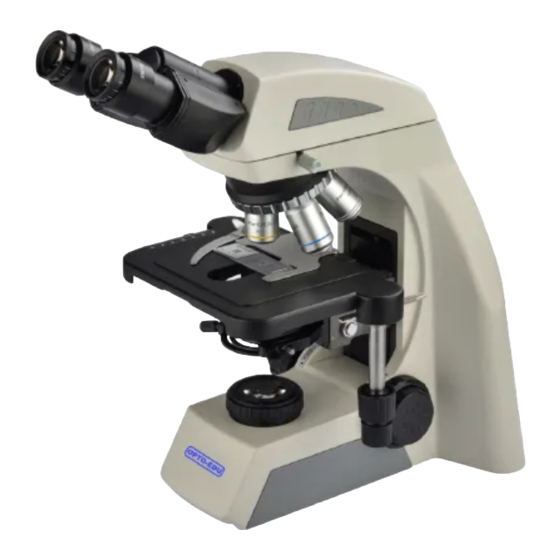
1. Components Name A12.1061 Eyepiece Viewing head Nosepiece Objective Condenser Stage Main body A12.1062 Digital Eyepiece viewing head Objective Encoded nosepiece Condenser Stage Main body... -
Page 6: Assembly
2. Assembly 2.1 Assembly Diagram The diagram below shows how to assemble the various components. The numbers indicate the order of assembly. When assembling the components, make sure that all parts are free of dust and dirt, and avoid scratching any parts or touching glass surfaces. ... -
Page 7: Assembly Procedure
2.2 Assembly Procedure 2.2.1 Installing the Objective(Fig.1-2) Adjust the coarse focus knob until the support device of the mechanical stage reach its low limit position. Screw the lowest magnification objective into the nosepiece from the left or the right side, then revolve the nosepiece clockwise/counterclockwise and mount other objectives by the sequence of low to high magnification. - Page 8 2.2.2 Connecting power cord (Fig.4-5) ★ The cable and cords are vulnerable when ① bent or twisted, never subject the power Ⅱ cord to excessive force. ③ ② Set the main switch① to “O” (off) state before Fig.4 connecting the power cord. Insert the plug②...
- Page 9 2.2.4 Mounting the filters(Fig.8) Place required filter into appropriate hole of the collector. Fig.8 2.2.5 LED lamp replacement ( Fig.9-11) ◎ Generally, LED lamp is very durable, so it is not easy to damage. If it is unfortunately damaged, please purchase the LED (Fig.11) from your vendors.
-
Page 10: Adjustment And Operation
3. Adjustment And Operation 3.1 Adjustment Set Diagram A12.1061 Interpupillar Distance Indicator Phase Contrast Slider Condenser Focusing Knob Aperture Diaphragm Tension Adjustment Collar Collector Field Stop Left Fine Focus Knob Brightness Adjustment Left Coarse Main Knob Focus Knob Switch... - Page 11 Portrait Adjustment Knob Lateral Adjustment Knob Right Fine Focus Knob Locking Knob Power Socket...
- Page 12 A12.1062 Interpupillary Distance Indicator Phase Contrast Slider Condenser Focusing Knob Aperture Diaphragm Collector Tension Adjustment Collar Filed Stop Left Fine Focus Knob LCD Screen Main Left Coarse Brightness Adjustment Switch Focus Knob Knob LCD Screen Number adjustable The symbol is converted Solid blue dot ”...
- Page 13 USB Interface Portrait Adjustment Knob Lateral Adjustment Knob Right Fine Focus Knob Locking Knob Power Socket...
-
Page 14: Operation
3.2 Operation 3.2.1 Brightness Adjustment (Fig.12-15) Connect the power cord and set the main switch ① on the right side of microscope to “-”state (ON). ① ② Turning the brightness adjustment knob Fig.12 ② in the direction shown in the figure, the voltage raise, and the brightness strengthen;... - Page 15 3. Double-click Knob: lock brightness or unlock (Fig.15). brightness adjustment knob fails when locking, and ”LOCK” appears on the LCD screen; Double-click the knob again to release the lock and the “LOCK” on the screen disappears; 1. Press + upward rotation: switch to Fig.15 up lighting;...
- Page 16 3.2.2 Placing the Specimen(Fig.16-17) Place the specimen in the center of the mechanical stage and use the stage clips to clamp it. Turn the portrait and lateral adjustment ① knob①of the mechanical ruler, move the specimen to the required position. Fig.16 ★...
- Page 17 3.2.5 Adjusting the tension adjustment collar(Fig.20) ★ The tension of the coarse focus knob had already adjusted before leaving factory. If it is too loose(the mechanical stage slides down because of its own weight), please ① turn the tension adjustment collar① until the tightness is appropriate.
- Page 18 3.2.7 Adjustment of Field Stop (Fig.22) ③ Turn the field stop ring③ in the direction shown in the figure to close the filed stop. Turn the field stop ring in the opposite direction to increase the filed stop. According to the magnification of the objective, adjust filed stop until...
-
Page 19: Video Attachment
4.1 Installing Trinocular Viewing Head And Video Attachment(Fig.25) 1. Mount the trinocular viewing head according to the assembly path① in Fig.25 into the ③ round dovetail of the microscope and Ⅲ tighten the screwⅠto fix the viewing head; 2. Mount the video attachment according to the assembly path②... -
Page 20: Digital Viewing Head
5. Digital Viewing Head Digital Viewing Head (Fig.27-28) There are two types of digital viewing heads to choose from: wired digital viewing head(Fig.27) and wireless digital viewing head(Fig.28). 1. The wired digital viewing head only has Fig.27 one interface. It is connected to the computer through the data line. -
Page 21: Fluorescent Observation
6. Fluorescent Observation A16.1062 6.1 Fluorescent Set(Fig.30-31) The fluorescent set uses 3W LED as illuminant fluorescence modules: B band fluorescence module and G band fluorescence module or U band fluorescence module. When the lever① is adjusted to the leftmost end, it is B band ①... -
Page 22: Phase Contrast Observation
7. Phase Contrast Observation 7.1 Components Name 7.1.1 Phase Contrast Objective The optional objective magnification of the phase contrast is :10×,20×,40×,100×. If you want to know how to mount the phase contrast objective, please see 2.2.2 . You ought to mount it on the nosepiece. - Page 23 (Fig.35) 7.2.2 Centering Diaphragm Generally do not need to center. If necessary, please adjust the diaphragm according to the following steps: 1. Place the specimen on the stage and focus 2. Take out a eyepiece and replace it with the centering telescope(CT).
-
Page 24: Dark Field Observation
8. Dark Field Observation 8.1 Bright and Dark Filed Components (Fig.36) The halo ① used in the dark filed observation is dark filed illumination board, while the opening② is used for bright filed ① ② Fig.36 8.2 Installation and Use(Fig.37) 1. -
Page 25: Simple Polarization Set
9. Simple Polarization Set 9.1 Components Name 9.1.1 Polarization Set(Fig.38) Polarization observation necessary components: polarizer① and ② ① analyzer②.The analyzer can be rotated at 0-90° . In orthogonal polarization observation, it is necessary to turn the analyzer to make the vibration directions of the polarizer and the analyzer perpendicular to each other and the filed Fig.38... -
Page 26: Technical Specifications
10.Technical Specifications 1、Main Specifications A12.1061, A12.1602 Laboratory Microscope A12.1061 A12.1062 A16.1062 LED Fluorescent Microscope ● ● ● ● Optical System NIS Infinite Optical System ● ● ● ● Bright Field ○ ○ ○ ○ Dark Field Observation ○ ○ ○... -
Page 27: Trouble Shooting
● ● Quintuple Nosepiece, Dovetail Interface Nosepiece ● ● Coded Quintuple Nosepiece, Dovetail Interface ● ● 4x/0.10, W.D.20.6mm ● ● 10x/0.25, W.D.17.9mm ○ ○ 20x/0.40, W.D.6.40mm NIS45 ● ● Infinity Plan 40x/0.60, W.D.1.50mm Objective ○ ○ 60x/0.80, W.D.0.30mm ● ● 100x/1.25(Oil), W.D.0.16mm ○... - Page 28 Double Layer Mechanical Rackless Stage, Size ● ● 230x150mm, Moving Range 78x54mm, Anti-Scratch Hard Coating Dural Platform Inserted Abbe Condenser N.A. 1.25, With Slot For ● ● ● ● Condenser Phase Contrast Slide And Dark Field Slide. ● ● 1W S-LED Critical Illumination ●...
- Page 29 2、Objective Parameters Numerical Working Conjugate Type Magnification Aperture Distance(mm) Distance (N.A) ∞ 4× 0.10 20.6 ∞ 10× 0.25 17.9 Plan Achromatic ∞ 20× 0.40 Objective(NIS45) ∞ 40× 0.65 ∞ 100× (Water) 0.16 ∞ 2× 0.06 ∞ 4× 0.10 ∞ 10× 0.25 10.2 Plan Achromatic...
- Page 30 TROUBLE CAUSE SOLUTION The nosepiece is not in the Turn to the location (the The edge of the located position (objective and objective enter the optical field of view is light path not coaxial) path correctly) dark The phase contrast slider is not Turn the slider into the brightness is not located in the proper position...
- Page 31 Reinstall the condenser Condenser properly and center the condenser centered or inclined One side of with the centering screw image is blurred The nosepiece is not properly Engage the nosepiece engaged properly The specimen is not clamped Clamp it with stage clips The specimen slips on the stage Fix it The image shift...
- Page 32 TROUBLE CAUSE SOLUTION check the connection of No power supply the power cord lamp The connector of LED lamp is not cannot light properly inserted into the circuit Insert it correctly when the switch board is turned on The lamp is broken Replace it Use the specified lamp to replace,if the problem...
Need help?
Do you have a question about the A12.1061 and is the answer not in the manual?
Questions and answers