Table of Contents
Advertisement
Quick Links
A12.1095
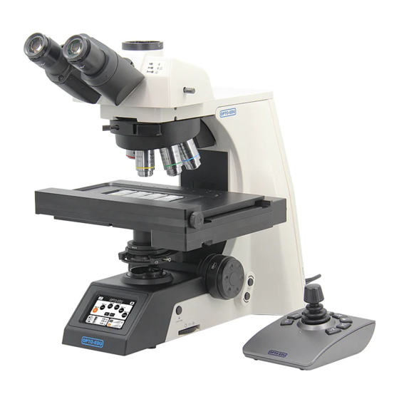
Research Scientific Laboratory Microscope,
Full-Auto Motorized
Instruction Manual
This manual is for users of A12.1095 scientific research microscope. To ensure your safety,
obtain optimum performance, and to familiarize yourself fully with the use of this
microscope, we recommended that you study the instruction manual carefully.
Advertisement
Table of Contents

Related Manuals for OPTO-EDU A12.1095


Summary of Contents for OPTO-EDU A12.1095
- Page 1 Full-Auto Motorized Instruction Manual This manual is for users of A12.1095 scientific research microscope. To ensure your safety, obtain optimum performance, and to familiarize yourself fully with the use of this microscope, we recommended that you study the instruction manual carefully.
-
Page 2: Table Of Contents
Contents A12.1095 User Notices..................1、Components Name................2、Structure Overview................3、Adjustment And Operation............................ 3-1、Turn On The Power ......3-2、Adjust The Brightness and Switch Light Source................ 3-3、Light Source Socket ................3-4、Mount Specimen ............3-5、Adjust Interpupillary Distance ............3-6、Three Light Path Switching .................. -
Page 3: User Notices
User Notices A12.1095 Ⅰ.Safety Symbols Symbol Meaning Main power switch is on Main power switch is off Upper / Lower lighting When the light switching button is pushed-in, the light source on the top will open.When the light switching button is pushed-out, the light on the bottom will open. - Page 4 A12.1095 Ⅲ.Maintenance All the lenses have been well checked and adjusted. It is forbidden to disassemble them yourself. The nosepiece, coarse and fine focusing parts are so delicate that it is forbidden to disassemble them carelessly by yourself. Keep the instrument clean, wipe dust regularly, and be attention to avoid contaminating the optical elements especially.
-
Page 5: 1、Components Name
Components Name A12.1095 Eyepiece Viewing Head Nosepiec Objective Stage Condenser Main Body... -
Page 6: 2、Structure Overview
2.Structure Overview A12.1095 1 2 3 4 5 6 7 Shortcut LCD touch screen Adjustment hand wheel 10. Aperture iris diaphragm adjustment ring Frosted filter switch lever 11. Electric stage Hand wheel speed control button 12. Extended function board fastening screw Condenser adjustment knob 13. - Page 7 A12.1095 1. Light path selector rod 9. Ground lever 2. Fastening screw for condenser 10. Lamp housing socket 3. Condenser adjustment knob 11. Lamp room plug 4. Adjustment hand wheel 12. Power socket 5. Photo button 13. Main switch 6. Filed iris diaphragm adjustment ring 14.
-
Page 8: 3、Adjustment And Operation
3. Adjustment and Operation ① 3-1 Turn on the power(Fig.1) A12.1095 First turn the main switch ① on the back of the microscope body to the "○" (off) state. Insert the ⑦ power cord plug ⑤ safely into the socket ④ of the adapter to ensure good contact. -
Page 9: Mount Specimen
A12.1095 3-4 Placing the Specimen(Fig.4) Pull out the movable claw, put the specimen in the corresponding slot, loosen the movable claw and clamp the specimen. ★ Be careful when changing the objective. When the objective needs to be replaced after observing... -
Page 10: Focusing
A12.1095 3-7 Focusing(Fig.7) 1. When camera is not used Push the light path selector rod (as shown in Fig. 7) in completely and observe with binocular eyes. Use 10 × In order to prevent the specimen from colliding with the objective, the electric... -
Page 11: Adjusting The Condenser
3-8 Adjusting the condenser(Fig.8、9) A12.1095 The condenser and the objective are coaxial. It has been adjusted before leaving factory, so the ① ② ③ user needn’t to adjust them by self The highest position of the condenser has been adjusted before leaving factory, so the user needn’t to adjust them by self... -
Page 12: Using The Frosted Filter
A12.1095 3-9 Using the filter(Fig.10) In the normal using state , the frosted filter is at the push-in state.For dark field observation or phase contrast observation, press the lever to cut the frosted filter out of the light path and increase the brightness of view. -
Page 13: Additional Function Keys
3-12 Additional function keys (Fig.14) A12.1095 As shown in Figure 14, there are two function Up function key keys on both sides of the microscope. In the right function key area, the upper function key is to switch the converter clockwise and the lower function key is to switch the converter anticlockwise;... -
Page 14: 4、Installation
Fig.15 . Installation A12.1095 4-1 Installing Diagram The following figure shows the installation sequence of the components. The number in the figure shows the assembly steps. Before installing, be sure every components is clean, do not score any parts or glass surface. -
Page 15: Installing Steps
4-2Installation Steps dovetail bulge of the frame and slide down naturally until lower limit screw is limited. Then A12.1095 the screw I in Fig.2 is screwed inward with a wrench. ① Fig.1 4-2-2 Installing the mechanical stage Ⅰ... -
Page 16: Installing The Nosepiece
Ⅱ Fig.4 A12.1095 4-2-3 Installing the nosepiece(Fig.5) ③ Mount the nosepiece according to the assembly Ⅲ path③ in Fig.5 into the dovetail of the microscope and push it to the bottom, then tighten the screw of Ⅲwith universal wrench to fasten. -
Page 17: Installing The Objective
⑦ Fig.7 A12.1095 4-2-6 Installing the Objective(Fig.8) 1. Adjust the focusing hand wheel until the electric stage bracket drops to its lowest limit. 2. Touch the objective key on the LCD screen from left to right, and screw on the corresponding... -
Page 18: 4-2-8 Replacing The Camera Interface
A12.1095 4-2-8 Replacing the camera interface (Fig.10、11) As shown in the Fig.10, spin out the Ⅶ bolt a distance in the direction shown by the arrow and don’t tight the photography interface, then spin out it. As shown in the Fig.11, screw the camera interface into the ternary camera barrel to an appropriate position. -
Page 19: 5、Technical Specification
5.Technical specifications A12.1095 1. Main Technical Specification Optical system NIS60 Infinite optical system A12.1095 SeidentopfTrinocular Head,Inclined at 30° ,Interpupillary ● Viewing head 47-78mm ● Eyepiece Extra Wide Field Eyepiece EW10X/25 ● Nosepiece Electric Sextuple Nosepiece Infinite Plan Objective:4× ,10× ,20× ,40× ,100×... -
Page 20: 6、Troubleshooting
6.Troubleshooting A12.1095 6.1 Optical Part TROUBLE CAUSE SOLUTION Adjust it into the located The nosepiece is not in the located position( turning the objective to position( The objective is not in the The edge of the field let it in the center of the light... - Page 21 The brightness is not enough The position of condenser is too low Adjust its position The condenser is not centered Adjust it to center A12.1095 Mechanical Part TROUBLE CAUSE SOLUTION The image can’t focus The slide is on the reverse side...
- Page 22 Improper screen connection dashboard is normal and reconnect properly Install the drive software as USB connection failed Drive is installed per the instructions A12.1095 Stage is not working Check the internal connections Improper line connection properly and reconnect well Initialization cannot stop...
Need help?
Do you have a question about the A12.1095 and is the answer not in the manual?
Questions and answers