
Related Manuals for Zepro ZHZ 500


Summary of Contents for Zepro ZHZ 500
- Page 1 Installation Instruction Tail Lift ZHZ 500/600-850 ZEPRO Tel.: +46 (0)10-459 05 00 E-mail: zeprotech@hiab.com zepro.com 73161TL 2022-11-30...
-
Page 3: Table Of Contents
Main power cable, earth cable, main fuse and main switch ....21 Installation of license plate light ............22 Installation of connection ramp ............. 23 Armstops ....................23 Platform stop ..................23 Adjustment of tilt cylinder ..............24 Purging the cylinders ................25 www.zepro.com... - Page 4 10 Testing and verification ................. 34 10.1 Static test loading ................. 34 10.2 Dynamic test loading................35 10.3 Testing safety functions ................ 35 11 Specifications ....................36 11.1 Weights ....................36 11.2 Load centre ................... 37 12 Registration ....................38 www.zepro.com...
-
Page 5: Important Information
NOTE! refers to additional information that may help the reader understand, or perform, a given operation. Technical support If technical support is needed, please contact ZEPRO. Tel: +46 (0)10-459 05 04, E-mail: zeprotech@hiab.com. Always be ready to state the tail lift’s production number to guarantee you receive the correct information. -
Page 6: Identification
Properly assembled, this product meets relevant requirements according to EN 1756-1:2001 + A1:2008. Hydraulic oil If the hydraulic oil needs to be replenished, only the oil recommended by ZEPRO is permitted to be used. Hydraulic systems with hydraulic oil tanks without labelling are only permitted to be filled with highly refined mineral oil (art. no. 21963, 1 litre). -
Page 7: Repainting
ZHZ 500/600-850 Important information Repainting IMPORTANT Piston rods and cylinder covers must not be painted. Among other things, this can damage the cylinder gaskets. Boots, hydraulic hoses and cables may not be coated/painted as the solvent in the paint can damage the hoses and cables and impair durability. -
Page 8: Safety Rules
Connection of third-party equipment is forbidden WARNING! Connecting third-party equipment (electric or hydraulic) to Zepro tail lifts is forbidden. Connecting third-party equipment could interfere with the lift’s system and its safety functions. Risk of injury and damage. If it is necessary to install other equipment, check the vehicle manufacturer’s body instructions and use the at-... -
Page 9: Main Parts
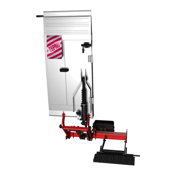
ZHZ 500/600-850 Main parts Main parts Platform Tilt cylinder Link Lift arm Frame Lift cylinder Support arm Step Fig 7. Overview www.zepro.com... -
Page 10: Before Installation
ZHZ 500/600-850 Before installation Before installation Calculating the installed dimensions For easier installation, it is useful to calculate and specify the necessary dimensions in advance. Determine the C-dimension first, then obtain the other dimensions from the relevant table. You should try to position the lift as high as possible within the specified C-dimension in the table. 4.1.1 C-dimension The C-dimension is the distance between the top the support frame and the vehicle floor level. This dimension governs how far the lift needs to be installed under the vehicle body (D-dimension) and the space between the lift arms in the upper position and the vehicle floor level (A-dimension). -
Page 11: Temporary Connection
ZHZ 500/600-850 Before installation Temporary connection When the tail lift is installed, it is sometimes necessary to operate its functions in order to change the position of the cylinders and the lift arms. Temporarily connect the lift to enable the lift functions. - Page 12 ZHZ 500/600-850 Before installation 4.2.2 Connecting the control device to the TLC-B1 relay card The connection of warning lights and the most commonly occurring controller (CD (Control Device)) models is shown below. Possible controller models vary depending on lift model, configuration and relevant market. WARNING! Make sure the control relay is disconnected from power before connecting. Connecting more than one controller to each connection is not permitted.
-
Page 13: Installation
ZHZ 500/600-850 Installation Installation Installing the lift 1. Mount the lift to the chassibracket without tightening the screws. The number of screws and theír placement depends on the type of bracket used, see installation instruction for the mounting kit in question. -
Page 14: Installing The Platform
ZHZ 500/600-850 Installation Installing the Platform 1. Remove the cover at the lower en of the platform, see Fig 10. 2. Push the shaft out off the platform, see Fig 11. 3. Position the platform on the lift arms, see Fig 12. 4. Push the shaft inwards until its flush with the platforms suface on the opposite side, see Fig 13:1. 5. Fit in the screw (attached), see Fig 13:2, to lock the platform shaft. -
Page 15: Installing The Angle Sensor
ZHZ 500/600-850 Installation Installing the angle sensor If the lift is equipped with radio control, associated angle sensor must be mounted on the platform, see Fig 15. Use sensor bracket, art. no. 53937TL (Ordered separately). 1. Mark the position of the bracket holes on the plat- form and drill suitable holes. -
Page 16: Installing The Hydraulic Unit
ZHZ 500/600-850 Installation Installing the hydraulic unit A suitable location for the hydraulic unit is on the wheel housing. The unit is ideally secured with the supplied bracket. The hydraulic unit can be installed horizontally or vertically. NOTE! Replace transport plug with regular tank cap before removing plugs in A and B. -
Page 17: Installation Of Connection Ramp
ZHZ 500/600-850 Installation Installation of connection ramp Install the connection ramp to that it connects 40-60 mm in on the platform. A safety distance of 75 mm is recommended when Connection ramp the platform is level with the vehicle floor. Fig 19. Connection ramp Armstops The armstops must be adjusted after installation of the installation kit and lift. -
Page 18: Adjustment Of Tilt Cylinder
ZHZ 500/600-850 Installation Adjustment of tilt cylinder WARNING! Take great care during test operation before adjusting the tilt cylinder to ensure that the vehicle body is not damaged. Make sure that the tilt cylinder is adjusted in such a way that the platform does not catch on the vehicle body when the platform is tilted up fully. -
Page 19: Purging The Cylinders
ZHZ 500/600-850 Installation 5.10 Purging the cylinders Purge the lift cylinders by lowering the platform all the way to the ground a few times. It may be necessary to raise the truck to allow the platform to be lowered completely. - Page 20 ZHZ 500/600-850 Installation 5.11 Control devices 300 - 600 mm. 1. Fit the controllers in the desired locations. How- ever, locate them such that the operator’s work- ing position is as safe as possible, and with an adequate overview of the load, tail lift and their working area.
- Page 21 ZHZ 500/600-850 Installation 5.12 Connection box If more than three controllers are to be connected or if two controllers with two-handed grip are to be con- nected, a connection box must be fitted. 1. Install the connection box in an appropriate location. 2. When fitting, the drainage tube must be facing downwards, see Fig 28. 3. Connection is described later in section 7.
- Page 22 ZHZ 500/600-850 Cable routing Cable routing General IMPORTANT In order to ensure a high degree of reliability for many years to come, it is important that components such as batteries, chargers, main current and earth cables, fuses and main switches are dimensioned correctly and assembled with great accuracy. Insufficient battery power can permanently damage the electrical components in the tail lift (solenoid, electric motor, solenoid valves, relay board/ control board and more.)
- Page 23 ZHZ 500/600-850 Cable routing Sizing electrical systems Ensure that the battery and charger capacity is sufficient for the product in question and that cable with suf- ficient cross-sectional area is used. ZHZ 500-850 (140 bar) 12 volt 24 volt Pump – Motor unit 100 A 60 A Magnet (hydr. unit) 4.2 A 0.7 A NOTE! Magnet (electrical hose rupture valve) 1.5 A 0.75 A...
- Page 24 ZHZ 500/600-850 Cable routing ZHZ 600-850 (190 bar) 12 volt 24 volt Pump – Motor unit 110 A 60 A Magnet (hydr. unit) 1.4 A 0.7 A Magnet (electrical hose rupture valve) 1.5 A 0.75 A Solenoid 1.8 A 0.9 A...
- Page 25 ZHZ 500/600-850 Cable routing Main power cable, earth cable, main fuse and main switch Main switch should always be mounted when cab switches (CS) are not used, for example when installing on trailers. Main switches can also be installed in combination with cab switches (CS) if desired.
- Page 26 ZHZ 500/600-850 Connection Connection Cable grommet 7.1.1 Before cable connection To be able to install/remove/adjust the cables in the cable grommet, the five screws must be loosened. 1. Loosen the five screws on the cable grommet, see Fig 35. Cables can now be installed/removed/adjusted in the grommet. The cable should be installed together with existing cabling using cable ties. Fig 35. The cable grommet's five screws Connection 1.
- Page 27 ZHZ 500/600-850 Connection Connecting the control device to the TLC-B1 relay card The connection of warning lights and the most commonly occurring controller (CD (Control Device)) models is shown below. Possible controller models vary depending on lift model, configuration and relevant market. WARNING! Make sure the control relay is disconnected from power before connecting. Connecting more than one controller to each connection is not permitted.
- Page 28 ZHZ 500/600-850 Connection Connection card www.zepro.com...
- Page 29 ZHZ 500/600-850 Connection 7.5.1 Scotchlok IMPORTANT When using Scotchlok, make sure all cables are correctly positioned and use a suitable plier to acheev correct clamp connection. Bad connection can cause mall function and material damage on the equippment. www.zepro.com...
- Page 30 ZHZ 500/600-850 Connection Cab switch and open platform alarm www.zepro.com...
-
Page 31: Electrical And Hydraulic Drawings
ZHZ 500/600-850 Electrical and hydraulic drawings Electrical and hydraulic drawings ZHZ-500/600-850 MA www.zepro.com... - Page 32 ZHZ 500/600-850 Powering up the tail lift Powering up the tail lift 1. If applicable, ensure that the main switch is in the "Off" position. 2. If applicable, ensure that the cab switch (CS) is in the "Off" position. 3. When using a fuse box, connect the cable (1) to the battery’s positive terminal and to the fuse box and place the fuse (2) above, see Fig 36.
-
Page 33: Lubrication And Fluid Level Check
ZHZ 500/600-850 Lubrication and fluid level check Lubrication and fluid level check 10.1 Lubrication 850 is equipped with slide bearings that must NOT be lubricated. 10.2 Fluid level check Check the fluid level in the tank when performing servicing, top up if necessary. The marking on the hydraulic tank indicates the type of hydraulic fluid used. Mineral hydraulic fluid, product no. 21963 (1 Litre), or biode- gradable synthetic fluid, product no. 22235 (). www.zepro.com... -
Page 34: Markings And Decals
ZHZ 500/600-850 Markings and decals Markings and decals Below, an overview of the location of the different markings is shown. Image of markings and additional infor- mation can be found under the relevant subchapter for the following pages. 11.8 11.7 11.1 11.3 11.4 11.6 www.zepro.com... -
Page 35: Load Diagram
ZHZ 500/600-850 Markings and decals 11.1 Load diagram Affix the load diagrams for the appropriate lift model close to the primary controller and in a suitable clearly visible position on the vehicle body. Fig 41. Load diagram ZHZ 500 Fig 42. Load diagram ZHZ 600 www.zepro.com... -
Page 36: Work Area
ZHZ 500/600-850 Markings and decals 11.2 Identification plate The identification plate is fitted to the frame of the tail lift and contains the following information: • Type of lift • Maximum permitted load in kg • Production number • Year of manufacture • Address and telephone no. of manufacturer • Country of manufacture •... -
Page 37: Danger Area
ZHZ 500/600-850 Markings and decals 11.6 Danger area A “danger area” decal warns about the danger zone between the platform and the rear edge of the vehicle. The decal must be attached to the inside of the vehicle body, close to where the manual control device is installed. -
Page 38: Testing And Verification
ZHZ 500/600-850 Testing and verification Testing and verification Testing and verification of the tail lift is performed in accordance with installation/delivery inspection. Verify that the tail lift is suitable for the vehicle in question and for the intended use. 12.1 Static test loading 12.1.1 Deformation Position the tail lift halfway up to vehicle floor level and with the platform in the horizontal position. Measure dimensions A-B-C-D for comparison, as illustrated. Place a test load on the platform according to the table (for relevant tail lift model and lifting capacity). -
Page 39: Dynamic Test Loading
ZHZ 500/600-850 Testing and verification 12.2 Dynamic test loading. 12.2.1 Test with maximum load Place a test load on the platform according to the table (for relevant tail lift model and lifting capacity). Check that the lift operates correctly in the normal range of movement allowed, i.e. up, down, tilting at ground level and tilting at vehicle floor level. -
Page 40: Specifications
ZHZ 500/600-850 Specifications Specifications 13.1 Weights Many of the lift’s components are heavy and therefore have to be lifted into place with the aid of lifting equip- ment. Make sure that the weight of the components does not exceed the maximum permitted load for the lifting equipment. -
Page 41: Load Centre
ZHZ 500/600-850 Specifications 13.2 Load centre Max. load ZHZ 500-600, alu. platform 1200x1400 mm C = 150 C = 300 C = 450 (mm) (mm) 500 kg (mm) 600 kg www.zepro.com... -
Page 42: Registration
ZHZ 500/600-850 Registration Registration For the tail lift’s guarantee to be valid, the delivery card must be registered in C-care (www.c-office.com). The bodybuilder is responsible for registration in C-care and must certify in the intended location in tail lift's instruc- tion manual that it has been registered. www.zepro.com... - Page 43 ZHZ 500/600-850 Registration www.zepro.com...
- Page 44 BUILT TO PERFORM Zepro, Del and Waltco are Hiab brands for tail lifts. Hiab is a world-leading supplier of equipment, intelligent services and digital solutions for on-road load handling. As an industry pioneer our company commitment is to increase the efficiency of...
Need help?
Do you have a question about the ZHZ 500 and is the answer not in the manual?
Questions and answers