
Related Manuals for Zepro Z3N


Summary of Contents for Zepro Z3N
- Page 1 Technical Manual ZEPRO Tel.: +46 (0)10-459 05 00 Email: zeprotech@hiab.com zepro.com 79874TL 2024-01-30...
-
Page 3: Table Of Contents
Accessing the card and the hydraulic unit ..........7 Battery and cable requirements ..............8 Control cards ....................9 ZePRO1 circuit card ..................9 TLC B1 relay card ..................20 Troubleshooting ..................48 Causes of malfunctions ................48 Troubleshooting strategy ................. 48 www.zepro.com... -
Page 4: Product Overview
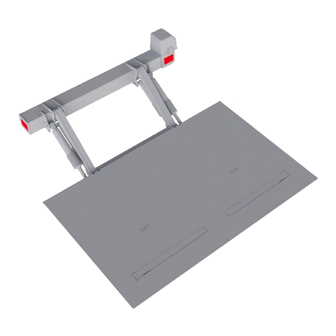
For the Z3N, the following nomenclature is used. The first three or four letters is the model designation where the Z3N is the standard model, the Z3NN is a model with a narrow support frame and the Z3NW is a model with a wide support frame. If the tail lift is equipped with an underrun protection devices, the letter "u" is added after the model designation. The two digit number denotes the lifting capacity of the lift, in kilograms, and the three digit number that follows is the approximate maximum lifting height of the lift in centimeters. - Page 5 Product overview 1.1.2 Main components All variants of the Z3N model family consist of the same main components shown in the figure below. www.zepro.com...
- Page 6 The control card converts the inputs from the user and the sensors into outputs to the motor solenoid and the valves which accomplish the desired motion. The Z3N can be equipped with one of two models of control cards, depending on market and required functionality. The first control card is the ZePRO1 control card which is an ad- vanced processor based circuit card.
-
Page 7: Accessing The Card And The Hydraulic Unit
The control card and the hydraulic unit are housed inside the box located on the right side on the tail lift. They are accessed by unlatching the two latches on the top and the bottom on the plastic cover and removing the cover. www.zepro.com... -
Page 8: Battery And Cable Requirements
The total length of the cable is measured according to the following figure. Some vehicle models have restrictions regarding the amount of current the lift can access from the existing battery. Some vehicle models do not fully charge the battery. It may therefore be necessary to switch to a bat- tery and sometimes also to a charger with a larger capacity. www.zepro.com... -
Page 9: Control Cards
Control cards Control cards ZePRO1 circuit card 2.1.1 Overview The ZePRO1 control card can be split into different functional sections as shown in the following figure. In- depth explanations of each section are contained in the following chapters. Fig 3. ZePRO1 control card www.zepro.com... - Page 10 This can be achieved by locking and unlocking with a code or an On/Off switch inside lockable driver's cab. The Zepro solution consists of a cab switch, which when active, sends power to the CS pin in the cab switch section of the card. When the switch is in its "Off" position any inputs are disregarded and the tail lift is efec- tively locked.
- Page 11 2 analog sensors, Ai1 and Ai2. The card can accomodate the sensors shown in the table. Different variants of the Z3N use different types and number of sensors, see the functional descriptions and schematics chapter for more information.
- Page 12 Secondary devices do not offer the possibility of two-handed operation and therefore unable to operate certain functions. The most common primary control devices for the Z3N are shown below. Fig 4. CD 19...
- Page 13 Control cards Fig 5. CD 1 Fig 6. CD 3 www.zepro.com...
- Page 14 The ZePRO1 control card has six control device inputs Ctrl 1 through Ctrl 6. • Ctrl 1 - Input for a primary control device. Can control all tail lift functions apart from slide in / slide out. • Ctrl 2 - Input for a primary control device. Same functionality as Ctrl 1. • Ctrl 3 - Input for a secondary control device such as radio control device with externally mounted receiver. • Ctrl 4 - Input for a secondary control device such as in-box mounted device with a spiral cable. • Ctrl 5 - Input used for the slide out / slide in functionality of sliders. Not used on the Z3N. • Ctrl 6 - Input used for the receiver of the radio control device. Same functionality as Ctrl 3. The most common secondary control devices for the Z3N are shown below. Fig 7. CD 9 Fig 8. CD 10 www.zepro.com...
- Page 15 Control cards Fig 9. CD 11 Fig 10. Receiver module is mounted directly on the control board. www.zepro.com...
- Page 16 LED2 is lit to indicate an active output. Startup sequence Every time the card is switched on, either by turning the cabin switch off and then back on or by cutting the power to the lift and turning it back on, a startup sequence is displayed on the display. The software configura- tion is displayed first, followed by the detected voltage and the firmware version number. It is crucial that the software configuration is the correct one for the tail lift it is installed on, see the software configurations chapter for more information. www.zepro.com...
- Page 17 The number will stop flashing when one of the current control device buttons is pressed. If the control card has been without voltage and receives the voltage again when the CS (cabin switch) is switched on, “7” will flash on the display and the control card is locked until the Off/On on the CS is operated. www.zepro.com...
- Page 18 U - Output not connected Fault code U is displayed when the card powers an output with nothing connected to it. The number 0-7 fol- lowing the letter U identifies the output in question, U0 through U7. The fault code is reset automatically when/if the card can detect normal current draw through the output. www.zepro.com...
- Page 19 U1-U3 are usualy used for valves V1, V2 and V3. U4 and U5 are usually used for the safety valves on the tilt and lift cylinders and the remaining ouput pins are used for adidional valves. See the functional descriptions and schematics chapter for more information. www.zepro.com...
-
Page 20: Tlc B1 Relay Card
Control cards TLC B1 relay card 2.2.1 Overview The TLC B1 control card can be split into different functional sections as shown in the following figure. In- depth explanations of each section are contained in the following chapters. Fig 11. TLC B1 control card www.zepro.com... - Page 21 This can be achieved by locking and unlocking with a code or an On/Off switch inside lockable driver's cab. The Zepro solution consists of a cab switch, which when active, sends power to the CS pin in the cab switch section of the card. When the switch is in its "Off" position any inputs are disregarded and the tail lift is efec- tively locked.
- Page 22 Fig 14. Supply socket for different sensors The TLC B1 card can accomodate the sensor types shown in the table below. Different variants of the Z3N use different types and number of sensors depending on functionality. See the functional descriptions and sche- matics chapter for connection information.
- Page 23 Secondary devices do not offer the possibility of two-handed operation and are therefore unable to operate certain functions. The most common primary control devices for the Z3N are shown below. Fig 15. CD 19 Fig 16.
- Page 24 Control cards The most common secondary control devices for the Z3N are shown below. Fig 18. CD 9 Fig 19. CD 10 Fig 20. CD 11 www.zepro.com...
- Page 25 LED on the strip. Sensors S2 through S4 have their own dedicated LED’s as well while S5 and S1 are grouped together into one LED. 2.2.6 Card configuration The card configuration block is a block with three switches that determines the configuration of the card. For the Z3N tail lift family, only the 000 configuration is used which means that all three switches are in their OFF position as shown below. 2.2.7 Outputs The output section is used for power delivery to the solenoid and the coils that control the valves and thereby the motion of the tail lift.
- Page 26 Control cards 3. Functional descriptions and schematics 3.1 Z3N 3.1.1 Description The Z3N, including variants such as the Z3NN and Z3NW, is a tail lift with two double acting tilt cylinders and a single acting lift cylinder. It is equipped with a quick opening valve that increases the opening speed of the platform. It is not equipped with auto tilt functionality. Sensors used: Angle sensor located on the platform used for the safety requirement for two hand operation when opening and closing against the boxy body.
- Page 27 Control input: Down + Tilt + 2H. Available on primary control devices only. Sensor input: Angle sensor on platform must be inactive at start of motion. Card indication ZePRO TLC-B1 Must be active for the function to be executed. Must be inactive for the function to be executed. Must be active or inactive, the function will be executed either way.
- Page 28 Description: Platform opening from fully closed against box body to horizontal. Control input: Down + Tilt + 2H. Sensor input: None required for function. Card indication ZePRO TLC-B1 Must be active for the function to be executed. Must be inactive for the function to be executed.
- Page 29 Description: Vertical platform lowering. Control input: Down. Available on all control devices. Sensor input: None required for function. Card indication ZePRO TLC-B1 Must be active for the function to be executed. Must be inactive for the function to be executed.
- Page 30 Description: Tilting down within +45/-10 degrees from horizontal. Control input: Down + Tilt. Available on all control devices. Sensor input: Active angle sensor on platform. Card indication ZePRO TLC-B1 Must be active for the function to be executed. Must be inactive for the function to be executed.
- Page 31 Description: Tilting up within +45/-10 degrees from horizontal. Control input: Up + Tilt. Available on all control devices. Sensor input: Active angle sensor on platform. Card indication ZePRO TLC-B1 Must be active for the function to be executed. Must be inactive for the function to be executed.
- Page 32 Description: Vertical platform raising. Control input: Up. Available on all control devices. Sensor input: None required for function. Card indication ZePRO TLC-B1 Must be active for the function to be executed. Must be inactive for the function to be executed.
- Page 33 Description: Closing fully against the box body. Control input: Up + Tilt + 2H. Available on primary control devices only. Sensor input: None reqiured for function. Card indication ZePRO TLC-B1 Must be active for the function to be executed. Must be inactive for the function to be executed. Must be active or inactive, the function will be executed either way.
- Page 34 Control cards 2.2.8 Summary of active valves Z3N Control input Sensor input Outputs ZePRO1 Card connection TLC-B1 Quick open Open High Lower High High...
- Page 35 Control cards 2.2.9 Z3N(U), Z3NN(U), Z3NW(U) 75-100 (TLC-B1) www.zepro.com...
- Page 36 Control cards 2.2.10 Z3N(U), Z3NN(U), Z3NW(U) 75-100 (ZePRO1) www.zepro.com...
- Page 37 Control cards Z3N with digital auto tilt Function: quick open Description: Quick platform opening from fully closed against box body to horizontal. Control input: Down + Tilt + 2H. Available on primary control devices only. Sensor input: Angle sensor on platform must be inactive at start of motion. Card indication ZePRO TLC-B1 Must be active for the function to be executed.
- Page 38 Control cards Z3N with digital auto tilt Function: open Description: Platform opening from fully closed against box body to horizontal. Control input: Down + Tilt + 2H. Sensor input: None required for function. Card indication ZePRO TLC-B1 Must be active for the function to be executed.
- Page 39 Control cards Z3N with digital auto tilt Function: auto tilt down Description: Automatic down tilting of the platform once gorund level has been reached. Control input: Down. Available on all control devices. Sensor input: Active pressure sensor on lift cylinder.
- Page 40 Control cards Z3N with digital auto tilt Function: manual tilt down Description: Tilting down within +45/-10 degrees from horizontal. Control input: Down + Tilt. Available on all control devices. Sensor input: Active angle sensor on platform. Card indication ZePRO TLC-B1 Must be active for the function to be executed.
- Page 41 Control cards Z3N with digital auto tilt Function: manual tilt up Description: Tilting up within +45/-10 degrees from horizontal. Control input: Up + Tilt. Available on all control devices. Sensor input: Active angle sensor on platform. Card indication ZePRO TLC-B1 Must be active for the function to be executed.
- Page 42 Control cards Z3N with digital auto tilt Function: auto tilt up Description: Automatic up tilting of the platform until it is tilted back to hori- zontal. Control input: Up. Available on all control devices. Sensor input: Active auto tilt angle sensor on platform.
- Page 43 Control cards Z3N with digital auto tilt Function: raise Description: Vertical platform raising. Control input: Up. Available on all control devices. Sensor input: None required for function. Card indication ZePRO TLC-B1 Must be active for the function to be executed.
- Page 44 Control cards Z3N with digital auto tilt Function: close Description: Closing fully against the box body. Control input: Up + Tilt + 2H. Available on primary control devices only. Sensor input: None reqiured for function. Card indication ZePRO TLC-B1 Must be active for the function to be executed. Must be inactive for the function to be executed.
- Page 45 Control cards 2.2.11 Summary of active valves Z3N www.zepro.com...
- Page 46 Control cards 2.2.12 Z3N(U), Z3NN(U), Z3NW(U) 75-100 electrical autotilt (TLC-B1) www.zepro.com...
- Page 47 Control cards 2.2.13 Z3N(U), Z3NN(U), Z3NW(U) 75-100 electrical autotilt (ZePRO1) www.zepro.com...
-
Page 48: Troubleshooting
Note that the troubleshooting steps listed above require the tail lift to be powered on and the cabin switch (if present) to be in the "ON" position. If the tail lift is completely dead, use a multimeter to troubleshoot the power supply starting at the tail lift and moving towards the battery. Possible causes include but are not limited to a dead battery, a tripped fuse or disconnected or damaged power and/or ground cables. www.zepro.com... - Page 50 BUILT TO PERFORM Zepro, Del and Waltco are Hiab trade marks for tail lifts. Hiab is a world-leading supplier of equipment, intelligent services and digital solutions for on-road load handling. As an industry pioneer, our company commitment is to increase the efficiency...
Need help?
Do you have a question about the Z3N and is the answer not in the manual?
Questions and answers