
Subscribe to Our Youtube Channel
Related Manuals for Timberwolf TW 125PH


Summary of Contents for Timberwolf TW 125PH
-
Page 1: Table Of Contents
CONTENTS Section Page No. INTRODUCTION PURPOSE OF MACHINE MACHINE DIMENSIONS & SPECIFICATIONS PARTS LOCATION DIAGRAMS 3 & 4 SAFE WORKING Operator’s Personal Protective Equipment Required Basic Woodchipping Safety General Safety Matters - Do’s and Dont’s Noise Test OPERATING INSTRUCTIONS Safe Transportation Hitching onto the Tow Ball Unhitching the Chipper Delivery... -
Page 2: Introduction
- damage to property - a member of the general public becoming injured This manual covers the operation and maintenance of the Timberwolf TW 125PH. All information in this manual is based on the latest product information available at the time. -
Page 3: Purpose Of Machine
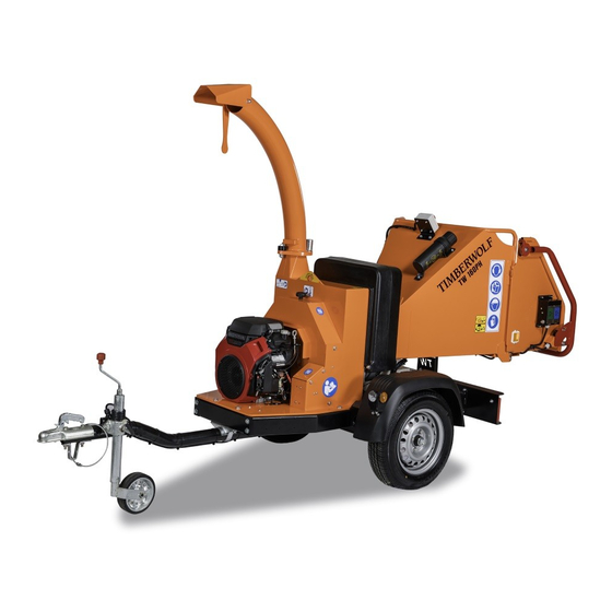
TIMBERWOLF 125PH PURPOSE OF MACHINE The Timberwolf TW 125PH brushwood chipper is designed to chip solid wood material up to 125 mm in diameter. It is capable of chipping over 2 tonnes of brushwood per hour. DIMENSIONS Serial No. Location... -
Page 4: Parts Location Diagrams 3
PARTS LOCATOR CONTROL BOX SPARE WHEEL DISCHARGE BUCKET SAFETY BAR DISCHARGE TUBE ROLLER BOX COVER DISCHARGE CLAMP NUTS FEED TRAY BELT GUARD FUNNEL ENGINE LIGHT BOARD BATTERY BOX COVER ROTOR HOUSING... - Page 5 PARTS LOCATOR PROP STAND ROLLER BOX ROTOR ROTOR DRIVE SECTION (x2) PULLEY HYDRAULIC PUMP CUTTER HYDRAULIC BLADE (x2) FUEL TANK PUMP BELT ADJUSTER HYDRAULIC OIL FILTER DIRECTIONAL CONTROL HYDRAULIC VALVE OIL TANK JOCKEY WHEEL ASSEMBLY BATTERY BELT TENSION ENGINE ENGINE ADJUSTER SHAFT PULLEY...
-
Page 6: Safe Working
SAFE WORKING WARNING The chipper will feed material through on its own. To do this, it relies on sharp blades both on the feed rollers and the chipper rotor. To keep the blades sharp, only feed the machine with clean brushwood. DO NOT put muddy/dirty wood, roots, potted plants, bricks, stones or metal into the chipper. -
Page 7: General Safety Matters - Do's And Dont's
SAFE WORKING GENERAL SAFETY MATTERS D O ’ S A N D D O N ’ T S ALWAYS stop the chipper engine before making DO NOT operate chipper unless available light is any adjustments, refuelling or cleaning. sufficient to see clearly. ALWAYS check rotor has stopped rotating and DO NOT... -
Page 8: Noise Test
SAFE WORKING NOISE TEST TW 125PH MACHINE: TESTED CHIPPING 65 mm X 75 mm CORSICAN PINE NOTES: 1.5m IN LENGTH Noise levels above 80dB (A) will be experienced at the working position. Wear ear protection at all times to prevent possible damage to hearing. All persons within a 4 metre radius must also wear good quality ear protection. -
Page 9: Operating Instructions
OPERATING INSTRUCTIONS SAFE TRANSPORTATION WARNING DO NOT RIDE ON THE CHIPPER WHEN IT IS BEING TOWED. WHEN towing a chipper the maximum speed limit is 60 mph. rough or bumpy road surfaces reduce speed accordingly to protect your machine from unnecessary vibration. -
Page 10: Delivery
OPERATING INSTRUCTIONS DELIVERY All Timberwolf TW 125 machines have a full pre - delivery inspection before leaving the factory and are ready to use. Read and understand this instruction manual before attempting to operate the chipper. In particular, read pages 5-7 which contain important health and safety information and advice. -
Page 11: Auto Controls
OPERATING INSTRUCTIONS AUTO CONTROLS The no stress unit controls the feed rate of the material going into the chipping chamber. If the rotor speed is below the predetermined level, the no stress unit will not allow the feed rollers to work in either forward or reverse, until the rotor speed rises above the predetermined level. -
Page 12: Before Using The Chipper
OPERATING INSTRUCTIONS BEFORE USING THE CHIPPER IT IS ESSENTIAL TO CARRY OUT THE FOLLOWING TESTS to check safety equipment - this sequence of tests will only take a few seconds to carry out. We recommend that these tests are carried out daily. Observing the function as described will confirm that the safety circuits are working correctly. -
Page 13: Starting To Chip
OPERATING INSTRUCTIONS STARTING TO CHIP WARNING Do not use or attempt to start the chipper without the protective guarding and discharge unit securely in place. Failure to do so may result in per- sonal injury or loss of life CHECK that the chipper is running smoothly. -
Page 14: Service Instructions
MAINTENANCE THAT SHOULD BE APPLIED TO ANY PIECE OF MECHANICAL EQUIPMENT AND THE CHASSIS TO WHICH IT IS MOUNTED. AUTHORISED TIMBERWOLF SERVICE AGENTS ARE FULLY TRAINED IN ALL ASPECTS OF TOTAL SERVICE AND MAINTENANCE OF TIMBERWOLF WOOD- CHIPPERS. YOU ARE STRONGLY ADVISED TO TAKE YOUR CHIPPER TO AN AUTHORISED AGENT FOR ALL BUT THE MOST ROUTINE MAINTENANCE AND CHECKS. -
Page 15: Service Schedule
Tow head maintenance. INSTRUCTION SHEET NOTE: Your Timberwolf woodchipper is covered by a full 12 months parts and labour warranty. Subject to correct maintenance and proper machine usage, the bearings are guaranteed for 12 months regardless of hours worked by the machine. In conditions of 'heavy usage' - i.e. in excess of 500 hours per year - it is recommended that the bearings are changed annually to ensure that the machine retains optimum working performance. -
Page 16: Engine Servicing
CHECK FITTINGS The Timberwolf TW 125PH is subject to large vibrations during the normal course of operation. Consequently there is always a possibility that nuts and bolts will work themselves loose. It is important that periodic checks are made to ensure the security of all fasteners. Fasteners should be tightened using a torque wrench to the required torque (see below). -
Page 17: Copper Ease Safety Information
SERVICE INSTRUCTIONS COPPER EASE SAFETY INFORMATION Product name: Copper Ease. Copper Ease contains no hazardous ingredients at or above regulatory disclosure limits, however, safety precautions should be taken when handling (use of oil-resistant gloves and saftey glasses are recommended - respiratory protection is not required). Avoid direct contact with the substance and store in a cool, well ventilated area avoiding sources of ignition, strong oxidising agents and strong acids. - Page 18 SERVICE INSTRUCTIONS BATTERY SAFETY INFORMATION...cont. 1. Storage and transport the positive output of the charger. Connect the - Batteries are filled with acid. negative terminal accordingly. - Always store and transport batteries upright - Switch on the charger only after the battery has and prevent from tilting so that no acid can been connected, and switch off the charger first escape.
-
Page 19: Change Blades
Remove blade access cover. at a later date and Timberwolf recommend you purchase a torque wrench for this and Remove discharge tube. Turn the rotor by hand other jobs on the chipper. -
Page 20: Tension Belts
NOTE: There will normally be a rapid drop in tension during run-in period for new belts. When new belts are fitted, check the tension every 2 - 3 hours and adjust until the tension remains constant. Belt failures due to lack of correct tensioning will not be covered under your Timberwolf warranty. TENSION DRIVE BELTS Remove belt guard. -
Page 21: Grease The Roller Spline And Bearing
SERVICE INSTRUCTIONS GREASE THE ROLLER SPLINE AND BEARING NOTE: This should be done regularly. In dirty and dusty conditions or during periods of hard work it should be weekly. If the bearings and splines are allowed to run dry premature wear will occur resulting in a breakdown and the need for replacement parts. -
Page 22: Warranty Statement
– in these situations they are duly authorised to transfer any remaining warranty period to their first end user. Any warranty offered by the Timberwolf Dealer beyond the original 12 month period will be wholly covered by said Dealer. -
Page 23: Ec Declaration Of Conformity Certificate
CERTIFICATE OF CONFORMITY... -
Page 24: Identification Plates
IDENTIFICATION PLATE The identification plate is normally located on the nearside chassis beam, close to the tow hitch (see page 2). -
Page 25: Decals 24
BRACKET IS ON THE INSIDE WHEN NEW BELTS ARE FITTED CHECK DAMAGED GUARDS DUE TO INCORRECT ASSEMBLY WILL NOT BE COVERED BY TENSION EVERY 2-3 HOURS & ADJUST YOUR TIMBERWOLF WARRANTY UNTIL TENSION REMAINS CONSTANT 4099 18393 18438 Last Updated 17th Jan 08... - Page 26 DECALS 671 - these individual decals are supplied as a set, they may not all apply to your machine.
-
Page 27: Electrical Detail
ELECTRICAL DETAIL... -
Page 28: Circuit Diagram
CIRCUIT DIAGRAM... -
Page 29: Hydraulic Layout
HYDRAULIC LAYOUT TANK FILTER HY2750 HY1421 PUMP HY1420 HY1423 HY1422 MOTOR MOTOR HY323... - Page 30 (blank)
-
Page 31: Parts Lists
TIMBERWOLF 125PH PARTS LISTS The following illustrations are for parts identification only. The removal or fitting of these parts may cause a hazard and should only be carried out by trained personnel. Page No. BELT TENSIONER CHASSIS CONTROL BOX DECALS... -
Page 32: Belt Tensioner
BELT TENSIONER Item Part No Part Name Q’ty 0313 M12/100 Bolt 0415 Heavy Washer 0491 Bearing 6205 0411M Pulley 0472M Pulley Boss N/A to purchase Slider 0469MS Slider Block 1342PS End Plate made in production Washer 0476 Plain M8 Nut Date Last Modified: 17th Aug 05 2988 M8/90 Bolt... -
Page 33: Chassis
CHASSIS Date Last Modified: 7th October 09 46 31 Item Part No Part Name Q’ty Item Part No Part Name Q’ty Item Part No Part Name Q’ty 1247 Prop Stand 0200 Wheel (inc. spare) 0067 Pop Rivet 0445 Light Board 0048 Mudguard 0382... -
Page 34: Control Box
CONTROL BOX Date Last Modified: 21st July 04 Item Part No Part Name Q’ty Item Part No Part Name Q’ty 2794FB Control Box Cover 0857 M5 A Washer 2803 M10/240 Bolt 18103 M5/8 Pan Pozi 0839 M10 C Washer 18168 M4/35 Pan Pozi 4345 M10 P Nyloc Nut... -
Page 35: Discharge
DISCHARGE Item Part No Part Name Q’ty 0904FO Discharge Tube 0523FO Discharge Bucket 0045 M12 T Nyloc Nut 0702 M12 A Washer 0320 M12/25 Cup Square 0430 M12/35 Cup Square 0134 Black Handle Grip 1649MS Discharge Clamp Handle 4109M M16 Clamp Nut 4131 Roll Pin 0434... -
Page 36: Drive Train
DRIVE TRAIN Date Last Modified: 10th Sept 09 Item Part No Part Name Q’ty Item Part No Part Name Q’ty 0994 Belt 950 1028S Trigger 0949M Pulley 140 X 1 SPA 0709 M6 C Washer 0412 Bush 1610 38 mm 1236 M6/20 Bolt 18961M... -
Page 37: Electrical Layout
ELECTRICAL LAYOUT Date Last Modified: 29th March 06 Item Part No Part Name Q’ty Item Part No Part Name Q’ty 1406 Limit Switch Loom 17398 No Stress Loom 1407 Control Box Loom 1401 Honda Adapter 1638 No Stress Sensor 0368 Battery - VE Battery Cable 3063... -
Page 38: Engine
ENGINE PARTS Date Last Modified: 3rd July 07 Item Part No Part Name Q’ty Item Part No Part Name Q’ty 1424 Foam Filter Element 4211F Muffler 1425 Paper Filter Element M8 Nut supp’d with engine 18252 Engine 0702 M12 A Washer 17318 Guard Top Engine 1426... -
Page 39: Funnel
FUNNEL Date Last Modified: 9th Oct 08 Item Part No Part Name Q’ty Item Part No Part Name Q’ty 2809F Control Box 1570 Safety Bar (detail on pg 33) 1721 M8/10 Bolt 1348 Limit Switch 0289FS Spare Wheel Bracket 1520 M10/45 Bolt 0045 M12 T Nyloc... -
Page 40: Hydraulics
HYDRAULICS Date Last Modified: 16th May 07 Item Part No Part Name Q’ty Item Part No Part Name Q’ty 2982 Hydraulic Motor 1703 Hydraulic Tank 0980 Hydraulic Pump 1413 Tank Top Filter 4252 Directional Control Valve (DCV) 0323 3/8” Hose, Top Motor to Btm Motor 1 1583 Adaptor mm 1/2”... -
Page 41: Roller Box
ROLLER BOX Date Last Modified: 8th May 07 Item Part No Part Name Q’ty Item Part No Part Name Q’ty 1673 M8 Wing Nut 0788 Plastic Bush 1595 Relay Cover 1362M Roller Body 0479 M8 P Nut 0325M Roller Blade 1672FS Relay Back Plate 0428... -
Page 42: Rotor
ROTOR PARTS Date Last Modified: 28th Feb 08 Item Part No Part Name Q’ty Item Part No Part Name Q’ty 0959 Plastic Cap 083MH Cutter Blade 4” 0884MS Bearing Housing Front 18275M Blade Pocket 18479K Rotor Nose Shaft Kit 0386 M10/30 Cap Screw 0880M Rotor... -
Page 43: Rotor Housing
ROTOR HOUSING PARTS Date Last Modified: 24th Jan 08 Item Part No Part Name Q’ty Item Part No Part Name Q’ty 0361 M12 Knob 0348 M6/20 Pozi Pan 0318 M12/20 Bolt 1416P Sensor Clamp 0704 M12 C Washer 0438 M6/16 Pozi Pan 0346 M8/20 Bolt 1410FO... -
Page 44: V-Belt Tensioning Table
V-BELT TENSIONING TABLE...
Need help?
Do you have a question about the TW 125PH and is the answer not in the manual?
Questions and answers