
Subscribe to Our Youtube Channel
Related Manuals for Intellisystem IT-IPS-316-IU-2GC-4-POE


Summary of Contents for Intellisystem IT-IPS-316-IU-2GC-4-POE
- Page 1 IT-IPS-316-IU-2GC-4-POE 4-Ports PoE 10/100Base-T(X) + 2-Ports Gigabit Combo Industrial PoE Switch User Manual...
-
Page 2: Packing List
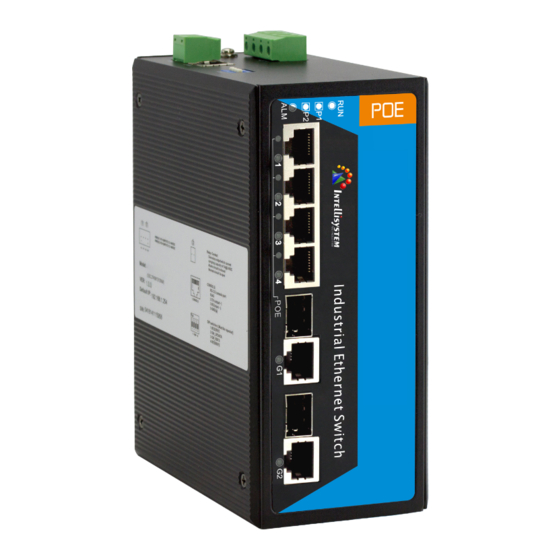
【Summarize】 IT-IPS-316-IU-2GC-4-POE is an industrial grade, managed and redundancy PoE Ethernet switch. The switch provides 4 ports 10/100M Ethernet and 2 ports combo Gigabit SFP slots or 10/100/1000Base-T(X) ports, which 4 ports Ethernet supports POE function (IEEE802.3af/at). The switches are classified as power source equipment (PSE), and when used in this way, the switches enable centralization of the power supply, providing up to 30 watts of power per port and reducing the effort needed for installing power. - Page 3 Front view Side view 1. Ground screw 2. Terminal block for power input (PWR1, PWR2) 3. Terminal block for relay output 4. Console port 5. DIP switches 6. DIN-Rail mounting kit 7. Relay alarm indicator 8. Power input P1 (P2) LED 9.
-
Page 4: Power Supply Input
【Power supply input】 The product top panel provided 4-bit power supply input terminal block, support DC input. DC power supply input supported redundancy function, provided PWR1 and PWR2 power input, can use for single, and can connect 2 separately power supply system, use 1 pair terminal block connect the device at the same time. - Page 5 In MDI/MDI-X, 100/1000Base-TX PIN defines is as follows: MDI-X BI_DA+/TX+ BI_DB+/RX+ BI_DA-/TX- BI_DB-/RX- BI_DB+/RX+ BI_DA+/TX+ BI_DC+/— BI_DD+/— BI_DC-/— BI_DD-/— BI_DB-/RX- BI_DA-/TX- BI_DD+/— BI_DC+/— BI_DD-/— BI_DC-/— Note: 10Base-T/100Base-TX, “TX±”transmit data±, “RX±”receive data±, “—”not use. 10/100Base-T(X) MDI (straight-through cable) 10/100Base-T(X) MDI-X (Cross-over cable) Gigabit MDI (straight-through cable)
-
Page 6: Gigabit Combo Port
Gigabit MDI-X (Cross-over cable) MDI/MDI-X auto connection makes switch easy to use for customers without considering the type of network cable. 1000Base SFP fiber port (mini-GBIC) 1000Base-X SFP fiber port adopts Gigabit mini-GBIC transmission, can choice different SFP module according to different transfer distance. Fiber interface must use for pair, TX port is transmit side, must connect to RX (receive side). -
Page 7: Led Indicators
【LED Indicators】 LED indictor light on the front panel of product, the function of each LED is described in the table as below. System indication LED State Description Power is being supplied to power input PWR input P (1~2) Power is not being supplied to power input PWR input When the alarm is enabled, power or the port’s link is inactive. -
Page 8: Specifications
Wiring Requirements Cable laying need to meet the following requirements: 1. It is needed to check whether the type, quantity and specification of cable match the requirement before cable laying; 2. It is needed to check the cable is damaged or not, factory records and quality assurance booklet before cable laying; 3. - Page 9 LED indicators Interface Link/Act indicator: Link (1~4/G1~G2) Power supply indicator: P1, P2 Run indicator: RUN Alarm indicator: ALM PoE indicator: POE (1~4) Power supply Input Voltage: 48VDC (44~57VDC) Type of input: 4 bits 7.62mm terminal block No-load consumption: 5.8W@48VDC Full-load consumption: 69W@48VDC Single PoE port maximum consumption: 30W@48VDC Support DC dual power supply redundancy Support DC input reverse connection protection...
Need help?
Do you have a question about the IT-IPS-316-IU-2GC-4-POE and is the answer not in the manual?
Questions and answers