Table of Contents
Advertisement
Quick Links
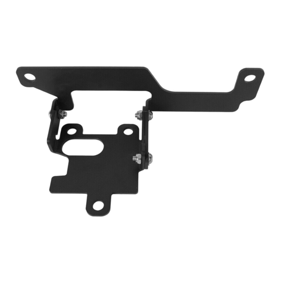
Adaptive Cruise Control Relocation Bracket
(1) Contents:
Qty
Part Name
1
Bracket Assembly
3
Button Head Socket Cap Bolts Screws
3
Button Head Socket Cap Bolts Screws
3
Flat Washer
Size(mm)
Qty
3
M8*30
3
M6*16
3
M6*13*1.5
FT.20009
Part Name
Nylon Insert Lock Nut
Nylon Insert Lock Nut
Flat Washer
Size(mm)
M6
M8
M8*16*1.5
Advertisement
Table of Contents

Related Manuals for HOOKE ROAD FT.20009


Summary of Contents for HOOKE ROAD FT.20009
- Page 1 Adaptive Cruise Control Relocation Bracket FT.20009 (1) Contents: Part Name Size(mm) Part Name Size(mm) Bracket Assembly Nylon Insert Lock Nut Button Head Socket Cap Bolts Screws M8*30 Nylon Insert Lock Nut Button Head Socket Cap Bolts Screws M6*16 Flat Washer M8*16*1.5...
- Page 2 About 2.5 hours, 1-2 people may be needed. Installation time may differ according to your mechanical skill level. (PLEASE VERIFY ALL PARTS ARE PRESENT AND READ INSTRUCTIONS CAREFULLY BEFORE STARTING INSTALLATION!) To view the electronic version (FT.20009), please scan the QR code.
- Page 3 (4) Installation instruction: Step 1: Begin by unpacking all items and inspecting for missing pieces or damage. If you have any concerns, please contact the company the product was purchased from. Hardware Included: (3)M6*15mm (3)M8*30mm (3)M6 Lock Nut (3)M8 Lock Nuts (3)M6 Flat Washer (3)M8 Flat Washers (6)D Spacers...
- Page 4 Step 3: Using an 8mm Socket, remove the three bolts holding the module in place. Step 4: Pull the module and bracket away from the vehicle slightly to expose the plug and squeeze down on the clip to release the module.
- Page 5 Step 5: Using a flat head screwdriver, wedge the tool in between the module and the bracket near each of the tabs and pull the module off the bracket. You will need to use firm pressure, but they should not be difficult to separate.
- Page 6 Step 7: To assemble the relocation bracket with the module, using the provided spacers, place them into the tabs of the module. Two spacers stacked on top of each other per tab (the spacers will only fit into one side of the tab, do not force them into the opposite side).
- Page 7 Step 9: With the module secure, attach the top bracket to the bottom bracket using the remaining M6 hardware. This will use a 10mm socket and a #3 allen head, however, leave loose enough to allow adjustment. Step 10: Next, the installation of the sensor bracket involves cutting. Please scan the QR code below to open the loading guide to complete the subsequent installation.
- Page 8 Step 11: The installation is complete. We hope you enjoy a wonderful off-road life with this quality Hooke Road product! Attention: 1.The product parts in this instruction may differ slightly from the actual product contents but generally does not affect the installation of the product.
Need help?
Do you have a question about the FT.20009 and is the answer not in the manual?
Questions and answers