Table of Contents
Advertisement
Quick Links
Bennett
Series
BlueFueler
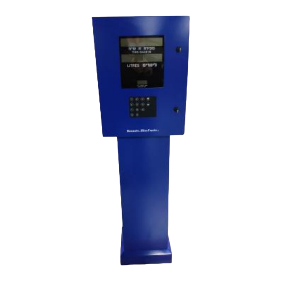
100 & 200 Series for Diesel Exhaust Fluid Dispensers
w/ 719 Electronics
Installation Manual
147193 Rev A 9/22/2021
Only Trained Personnel May Work on This Equipment
READ THIS MANUAL
This manual has important information for safe installation and operation of this equipment. Read and understand this manual before
applying power. Keep this manual and tell all service personnel to read this manual. If you do not follow the instructions, you can cause
bodily injury, death, or damage to the equipment.
Bennett 1218 E. Pontaluna Road, Spring Lake, MI 49456
USA 800-235-7618 ~ Outside USA 231-798-1310
sales@bennettpump.com ~ www.bennettpump.com
Advertisement
Table of Contents

Related Manuals for Bennett BlueFueler Series


Summary of Contents for Bennett BlueFueler Series
- Page 1 Keep this manual and tell all service personnel to read this manual. If you do not follow the instructions, you can cause bodily injury, death, or damage to the equipment. Bennett 1218 E. Pontaluna Road, Spring Lake, MI 49456 USA 800-235-7618 ~ Outside USA 231-798-1310...
- Page 2 For new manuals, visit our web page at IMPORTANT Examine the shipment immediately upon arrival to make certain there has been no damage or loss in transit. Bennett Pump Company, as shipper, is not liable for the hazards of transportation. Please make damage claims directly to the truck line.
-
Page 3: Table Of Contents
TABLE OF CONTENTS SECTION 1: SAFETY INFORMATION General Information ............................................4 Hazardous locations ............................................4 Codes and Standards............................................4 Unauthorized Alteration of Bennett Products ..................................4 Abbreviations and Acronyms ........................................4 SECTION 2: PRODUCT INTRODUCTION Features .................................................. 5 Specifications ............................................... 5 Determining the Model number ........................................ - Page 4 147193 Installation Manual DEF 100-200 Table of Contents Page Intentionally Left Blank...
-
Page 5: Section 1: Safety Information
Environmental Standards® Health, Safety, Security & Environment (HSSE) policies. Note: Bennett Pump highly recommends all technicians observe HSSE policies defined by the supplier. Bennett Pump does not impose any restrictions or additional requirements contained in Environmental Standards® Health, Safety, Security &... -
Page 6: General Information
American Petroleum Institute Recommended Practice RP 2003, Protection Against Ignitions Arising out of Static, Lightening, and Stray Currents. Service of the Bennett products and all accessories must be performed by a technician who is trained in accordance to all codes, standards, and regulations. -
Page 7: Section 2: Product Introduction
SECTION 2: PRODUCT INTRODUCTION The Bennett DEF 100/200 is a DEF only cabinet capable of Remote and Suction Models. It is intended for environments that will not freeze the fluid and will remain within the operating parameters of Diesel Exhaust Fluid. It is a single product, single hose unit with a very simple low profile cabinet. -
Page 8: Determining The Model Number
147193 Installation Manual DEF 100-200 Product Introduction DETERMINING THE MODE L NUMBER Determine the model number of the dispenser from the serial label located in the dispenser. Utilizing the chart below, determine the features of the dispenser to be installed. Understanding the features of the dispenser to be installed will be helpful understanding the proper installation of the dispenser. -
Page 9: Section 3: Installation Instructions
SECTION 3: INSTALLATION INSTRUCTIONS Bennett Pump Dispensers are to be installed by trained technicians. All technicians must be aware of ALL safety instructions. If you are not a Bennett trained technician, please contact Bennett Technical Support at 1-800-423-6638 for training information. -
Page 10: Piping Notes For Remote (Pressurized) Dispensers
All piping, hoses, and any fluid handling fittings must be approved materials compatible with AUS-32, (Diesel Exhaust Fluid). Make sure all local and national codes are followed during installation of the Bennett equipment. Follow Petroleum Equipment Institute’s RP1100 Recommended Practices for the Storage and Dispensing of Diesel Exhaust Fluid (DEF) Copies of PEI’s recommended practices can be ordered through their web site at: www.pei.org... -
Page 11: Piping Notes For Self-Contained (Suction) Pumps
147193 Installation Manual DEF 100-200 Installation Introduction PIPING NOTES FOR SELF-CONTAINED (SUCTION) PUMPS General - The total length of horizontal piping between the pump and tank must be no longer than 20 feet. Unit should be mounted on the same plane or as close to as possible on what the tote or tank will be set on. Static lift on self-contained units must not exceed 10 feet (vertical distance between product level in the storage tank and the center of the pumping unit). -
Page 12: Electrical Field Wiring- General Information
All conduit should be rigid metal and drawn up tight. The use of PVC (plastic) conduit is not allowed and will void the Bennett Warranty. Make sure any intercom wiring is not run with dispenser field wiring. -
Page 13: Purging Product Lines For Suction Pumps
147193 Installation Manual DEF 100-200 Installation Introduction Once product piping and tanks have been tested for leaks and any leak conditions have been fixed, and all electrical connections have been made and verified, the remote dispenser product lines must be purged of all air that may be trapped in the lines. -
Page 14: Pulling Field Wires
Step 5. Mechanical Pulse Output - If the dispenser is to be wired to a mechanical interface Card/Key system, the following wires will be needed: Note - A Bennett Pulse Output Board is required. Field wiring will be connected between this board and the third party interface system. This board will be mounted on the CPU inside the electronics enclosure. -
Page 15: Proper Equipment Grounding
INSTRUCTIONS FOR EARTH GROUNDING THE EQUIPMENT WARNING: Failure to properly ground the equipment can cause injury or damage to the equipment and will void the Bennett limited warranty. This product must be properly grounded. Each dispenser requires a 12-gauge Green earth ground wire. Grounding provides a path of least resistance for electric current to reduce the risk of electric shock. -
Page 16: Connecting Pump Motor Power For Remote Dispensers
147193 Installation Manual DEF 100-200 Installation Introduction Rules to ensure proper operation: Each dispenser uses one 115V or 230V circuit for dispenser power. Put no more than two (2) dispensers on a circuit breaker. Do not connect any other devices or motors to these circuits. Put the pump wiring in a dedicated separate conduit. -
Page 17: Connecting Field Wiring To Mechanical Pulse Output
This ensures that you are not taking your resistance reading across the electronics on the circuit board. If the resistance reading is more than 1 ohm, the dispenser electronics may not operate properly and will void the Bennett Limited Warranty. -
Page 18: How To Electronically Calibrate A Def Meter (E-Cal)
147193 Installation Manual DEF 100-200 Installation Introduction Turn on 115 or 230 volts AC dispenser power to the unit. 1. Use a voltmeter to verify 115 or 230 Volts AC only at Terminal 3 on TS1 of the CPU board. Terminal 2 of TS1 on the CPU board is Neutral. - Page 19 147193 Installation Manual DEF 100-200 Installation Introduction calibration switch and move the switch to the calibrate position. This brings up the test can size display. This switch is located on the top of the CPU board. NOTE: If local preset exists, that keypad will be used. With the Manager Keypad enter the size of the test can and press the ENTER button.
-
Page 20: Section 4: Footprints & Wiring Diagrams
Note - Dispenser electrical disconnect must comply with National Electrical Code, NFPA 70. WARNING: All doors must be replaced and locked when unit is in service. WARNING: Do not operate pump with door removed except when required for maintenance by a Bennett Authorized Service Representative. -
Page 21: Def 100/200 Footprint
147193 Installation Manual DEF 100-200 Installation Introduction DEF 100/200 FOOTPRINT... - Page 22 147193 Installation Manual DEF 100-200 Installation Introduction...
-
Page 23: Electrical Wiring Diagrams
147193 Installation Manual DEF 100-200 Installation Introduction ELECTRICAL WIRING DI AGRAMS... - Page 24 147193 Installation Manual DEF 100-200 Installation Introduction...
-
Page 25: Communication Wiring Diagrams
147193 Installation Manual DEF 100-200 Installation Introduction COMMUNICATION WIRING DIAGRAMS... - Page 26 147193 Installation Manual DEF 100-200 Installation Introduction...
- Page 27 147193 Installation Manual DEF 100-200 Installation Introduction...
- Page 28 147193 Installation Manual DEF 100-200 Installation Introduction...
Need help?
Do you have a question about the BlueFueler Series and is the answer not in the manual?
Questions and answers