Table of Contents
Advertisement
Quick Links
Bennett
Series
BlueFueler
100 & 200 Series for Diesel Exhaust Fluid Dispensers
w/ 719 Electronics
Operators Manual
147194 Rev A 9/22/2021
Only Trained Personnel May Work on This Equipment
READ THIS MANUAL
This manual has important information for safe installation and operation of this equipment. Read and understand this manual before
applying power. Keep this manual and tell all service personnel to read this manual. If you do not follow the instructions, you can cause
bodily injury, death, or damage to the equipment.
Bennett 1218 E. Pontaluna Road, Spring Lake, MI 49456
USA 800-235-7618 ~ Outside USA 231-798-1310
sales@bennettpump.com ~ www.bennettpump.com
Advertisement
Table of Contents

Related Manuals for Bennett BlueFueler Series


Summary of Contents for Bennett BlueFueler Series
- Page 1 Keep this manual and tell all service personnel to read this manual. If you do not follow the instructions, you can cause bodily injury, death, or damage to the equipment. Bennett 1218 E. Pontaluna Road, Spring Lake, MI 49456 USA 800-235-7618 ~ Outside USA 231-798-1310...
- Page 2 For new manuals, visit our web page at IMPORTANT Examine the shipment immediately upon arrival to make certain there has been no damage or loss in transit. Bennett Pump Company, as shipper, is not liable for the hazards of transportation. Please make damage claims directly to the truck line.
-
Page 3: Table Of Contents
TABLE OF CONTENTS SECTION 1: SAFETY INFORMATION General Information ............................................5 Hazardous locations ............................................5 Codes and Standards............................................5 Unauthorized Alteration of Bennett Products ..................................5 Abbreviations and Acronyms ........................................5 SECTION 2: PRODUCT INTRODUCTION Features .................................................. 6 Specifications ............................................... 6 Determining the Model number ........................................ - Page 4 147194 Operators Manual DEF 100-200 Table of Contents electrical wiring diagrams ..........................................37 communication wiring diagrams ......................................37...
- Page 5 147194 Operators Manual DEF 100-200 Table of Contents Page Intentionally Left Blank...
-
Page 6: Section 1: Safety Information
Environmental Standards® Health, Safety, Security & Environment (HSSE) policies. Note: Bennett Pump highly recommends all technicians observe HSSE policies defined by the supplier. Bennett Pump does not impose any restrictions or additional requirements contained in Environmental Standards® Health, Safety, Security &... -
Page 7: General Information
American Petroleum Institute Recommended Practice RP 2003, Protection Against Ignitions Arising out of Static, Lightening, and Stray Currents. Service of the Bennett products and all accessories must be performed by a technician who is trained in accordance to all codes, standards, and regulations. -
Page 8: Section 2: Product Introduction
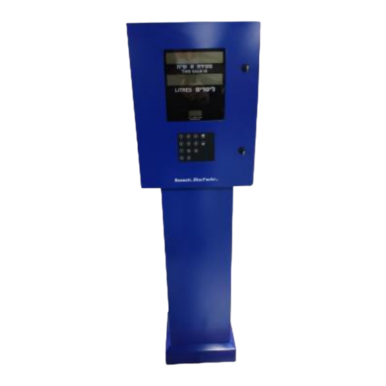
It has an external hose, so it can be installed in any climate not requiring any type of heating. It uses the basic oval gear meter used in other Bennett applications, with a ¾” two stage valve and interfaced with the Bennett 719 Electronics. -
Page 9: Determining The Model Number
147194 Operators Manual DEF 100-200 Product Introduction DETERMINING THE MODE L NUMBER Determine the model number of the dispenser from the serial label located in the dispenser. Utilizing the chart below, determine the features of the dispenser to be installed. Understanding the features of the dispenser to be installed will be helpful understanding the proper installation of the dispenser. -
Page 10: Section 3: Pump Operation
SECTION 3: PUMP OPERATION Bennett Pump Dispensers are to be installed by trained technicians. All technicians must be aware of ALL safety instructions. If you are not a Bennett trained technician, please contact Bennett Technical Support at 1-800-423-6638 for training information. - Page 11 147194 Operators Manual DEF 100-200 Operation Introduction The Manager Keypad. The manager keypad allows the dispenser to be programmed. When the manager keypad is plugged into the J11 connector on the CPU board, the “+/-” and “Enter” button are pressed simultaneously for 3 seconds, the dispenser enters the attendant mode (sometimes referred to as “manager’s mode”).
- Page 12 147194 Operators Manual DEF 100-200 Operation Introduction AC OFF Figure 3 The Last Sale Recall Switch. See Figure 4. During a power outage, the last sale can be recalled and viewed. Using a magnet reference below where to place the magnet. Press the kill switch to blank the screen, or wait 30 seconds, it will go out. The display will go blank until normal power returns.
- Page 13 147194 Operators Manual DEF 100-200 Operation Introduction resolved and the dispenser is returned to normal operation. Service Light Figure 6 The Flow Sensor Override Switch. See Figure 7. The flow sensor override switch is located inside the electronics enclosure on the upper left side. It is designed to override the flow sensor while purging air from the lines with new product.
- Page 14 147194 Operators Manual DEF 100-200 Operation Introduction Figure 8 The Pump Handle. See Figure 9. (Lift Lever Operation) The pump handle is located on the side of the dispenser. To operate the dispenser, remove the nozzle from the holder and lift the pump handle up for the ON position. Push the pump handle down for the OFF position. These are referred to as “Lift to Start”...
- Page 15 147194 Operators Manual DEF 100-200 Operation Introduction MODE ENTER Figure 10...
-
Page 16: Dispensing Product
Note: Because of rounding methods used and the nature of electronic totals versus an analog device such as an electro-mechanical totalizer, electronic totals and electro-mechanical totals will rarely match exactly. Displaying Electronic Totals - To display electronic totals on the BlueFueler Series retail dispenser, access menu code 1 or view the totals through the audit trail. -
Page 17: Viewing The Audit Trail
The Audit Trail is required by certain local regulations to be displayed when activated. A Magnet is shipped with each dispenser (Bennett p/n 114745). To activate the Audit Trail follow the same procedure as used for accessing the electronic totals. -
Page 18: Dispenser Programming Codes
147194 Operators Manual DEF 100-200 Operation Introduction Connecting the Manager keypad for dispenser programming. Programming is done from the manager keypad located inside the electronics compartment. To enable the dispenser for programming: 1. Remove the keypad and cable from the plastic bag located on the inside of the electronic enclosure. Connect the cable to the Manager Keypad. - Page 19 147194 Operators Manual DEF 100-200 Operation Introduction Initial Set Up Menu Code Initial Setup Default Setting Managers Access Code 2218 Pump Type Sides = 1, Grades = 1, Hoses = 1, Tier = 1 Pricing – For each hose and 1 or 2-tier pricing 0000 Communication Type (Current Loop, Stand Alone, RS485, 0 = Console Mode...
-
Page 20: Factory Code Settings
147194 Operators Manual DEF 100-200 Operation Introduction FACTORY CODE SETTINGS The software program for each new dispenser shipped from the factory is preprogrammed with default settings in some of the Menu Codes. Some menu codes must be changed immediately to make the dispenser operational. See the initial setup sequence below. -
Page 21: Changing The Manager Access Code
147194 Operators Manual DEF 100-200 Operation Introduction To access the Manager’s Mode, follow this procedure: Press the 3 button and then the MODE button on the keypad. 2. Enter the default number 2218. Four dashes appear in the display. 3. Press the ENTER button. When access is gained, the four dashes disappear. If the dashes do not move, the access code entered did not match the code stored in memory. -
Page 22: Reading Electronic Totals - Menu Code 01
147194 Operators Manual DEF 100-200 Operation Introduction READING ELECTRONIC T OTALS – MENU CODE 01 This menu code allows the manager to read the electronic non-resettable hose totals that accumulate in the dispenser for money, volume, number of sales, and number of price changes. To read the electronic totals: 1. -
Page 23: Changing The Dispenser Parameters - Menu Code 07
147194 Operators Manual DEF 100-200 Operation Introduction CHANGING THE DISPENSER PARAMETERS – MENU CODE 07 The Dispenser is programmed in the factory based on the DIN. In The Menu Code the main parameters of the Dispenser are set including the number of sides, number of Grades, Number of Hoses and Single vs Two tier pricing. To Change the Parameters, follow this procedure: 1. -
Page 24: Setting The No Flow Timeout - Menu Code 09
147194 Operators Manual DEF 100-200 Operation Introduction DECIMAL PLACEMENT SELECTIONS MONEY VOLUME DISPLAY DISPLAY DISPLAY Volume Selection Money Gallons / Liters Price [ 1.23] [1.234] [ 1.23] [1.234] [ 1.23] [1.234] [ 1.23] [12.34] [ 1.2] [1.234] [ 1.23] [12.34] [ 1.2] [1.234] [ 1.23]... -
Page 25: Setting The Slow Flow Amount - Menu Code 10
147194 Operators Manual DEF 100-200 Operation Introduction NOTE: If an error is made, press the 0 button until all three digits are zeros and enter a new number, or push number buttons until the correct number of seconds appears in the volume display. 4. -
Page 26: Setting Submerged Pump Pre-Charge Time - Menu Code 12
147194 Operators Manual DEF 100-200 Operation Introduction programmed at the factory to stop the flow of product at 999 volume units. The maximum volume limit is 99999 for gallons and 999999 for liters. The minimum volume limit is 1 unit. NOTE: Some control consoles will overwrite the volume allocation limit. -
Page 27: Setting The Dispenser Mode Of Operation - Menu Code 21
4- RS-485 Fleet for pulse output interface. Current Loop - Bennett Current Loop Protocol to consoles that support Bennett Current Loop Protocol. Stand Alone - Use the Stand Alone Mode when operating the dispenser without the use of a console or control system. -
Page 28: Viewing The Electronic Calibration - Menu Code 27
147194 Operators Manual DEF 100-200 Operation Introduction This menu code allows the Manager to set a dispenser address for each dispenser when multiple positions are on the same communications loop. Mode 22 is generally used with the RS485 communication protocol or RS485 via the Pulse Output Board. -
Page 29: Performing A Cold Start On The Dispenser - Menu Code 58
147194 Operators Manual DEF 100-200 Operation Introduction Dollar: Petrol: 10:1 10:1 100:1 100:1 1000:1 Select either option 1 – 4 depending on the desired ratio. Press Enter twice The pulse Rate selections can be set for the below options. It is set in “PPS” or Pulse per second. 1000 PPS 500 PPS 250 PPS... -
Page 30: How To Electronically Calibrate A Def (E-Cal) Menu Code 27
147194 Operators Manual DEF 100-200 Operation Introduction To select a different option in Menu Code 99, follow this procedure: 1. After the Manager Mode has been accessed, press the number 9 and 9, then the MODE button on the keypad. If the dispenser has not been programmed since it came from the factory, the Unit “US Gal”... -
Page 31: Viewing The Electronic Calibration Correction Constant
147194 Operators Manual DEF 100-200 Operation Introduction meter is out of calibration, write down the amount of the error from the test can sight glass. Repeat step 6. Move the calibration switch back to the operate position and seal it. Disconnect the Manager Keypad. The Direct Percent Entry Procedure The direct percent entry procedure provides a way of zeroing or overwriting the electronic calibration constant. - Page 32 147194 Operators Manual DEF 100-200 Operation Introduction .5 - ColdSt (Cold Starts Counter) .6 - FActrY (Reset to Factory Defaults Counter) .7 - Er Ct - (Number of Errors Counter) .8 - Pr Ch - (Price Changes Counter) By performing a diagnostic test, the operator or manager can inform the service technician of the problem before coming to the site.
-
Page 33: Error Codes
147194 Operators Manual DEF 100-200 Operation Introduction The display window shows the number of errors. If there are errors recorded, press enter and the displays read as in Figure 4. The first two digits represent how many times the error occurred, the two digits after the “E” represent the error code number. Note: These error messages can be cleared by activating and deactivating the on/off mechanism Note: These error messages will not allow the dispenser to function until the unit is restarted. - Page 34 147194 Operators Manual DEF 100-200 Operation Introduction RFLO C REVFLO C Detected Pulser C Rotating Backwards RFLO D REVFLO D Detected Pulser D Rotating Backwards PLSRAS PULSERAS Pulser A Error Same State Transition Limit Exceeded PLSRAN PULSERAN Pulser A Next State Transition Limit Exceeded PLSRAR PULSERAR Pulser A Reverse Flow...
- Page 35 147194 Operators Manual DEF 100-200 Operation Introduction VSIDE1 VACSIDE1 Vapor Vacuum – Side 1 Error – Fast Flow or Over Current VSIDE2 VACSIDE2 Vapor Vacuum – Side 2 Error – Fast Flow or Over Current VAPOR VAPOR TST Vapor Recover Error Signal Received PLSRDC PDISCONN Pulser Disconnected...
-
Page 36: Section 5: Warranty & Audit Form
SECTION 5: WARRANTY & AUDIT FORM AUDIT FORM Bennett 1218 E. Pontaluna Road, Spring Lake, MI 49456 USA 800-235-7618 ~ Outside USA 231-798-1310 sales@bennettpump.com ~ www.bennettpump.com... - Page 37 147194 Operators Manual DEF 100-200 Operation Introduction...
-
Page 38: Warranty Statement
147194 Operators Manual DEF 100-200 Operation Introduction WARRANTY STATEMENT... -
Page 39: Def 100/200 Footprint
147194 Operators Manual DEF 100-200 Operation Introduction DEF 100/200 FOOTPRINT ELECTRICAL WIRING DI AGRAMS COMMUNICATION WIRING DIAGRAMS... - Page 40 147194 Operators Manual DEF 100-200 Operation Introduction...
Need help?
Do you have a question about the BlueFueler Series and is the answer not in the manual?
Questions and answers