Table of Contents
Advertisement
Quick Links
LB management
KNX RF push-button
KNX RF push-button 1-gang
Art. no.: ..10911STRF..
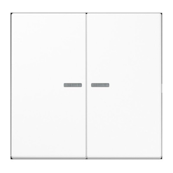
KNX RF push-button 2-gang
Art. no.: ..10921STRF..
Operating instructions
1
Safety instructions
Electrical devices may only be mounted and connected by electrically skilled persons.
Serious injuries, fire or property damage possible. Please read and follow manual fully.
Danger of electric shock. Always disconnect before carrying out work on the device or load. In
so doing, take all the circuit breakers into account, which support dangerous voltages to the
device and or load.
The radio communication takes place via a non-exclusively available transmission path, and is
therefore not suitable for safety-related applications, such as emergency stop and emergency
call.
These instructions are an integral part of the product, and must remain with the end customer.
32403803
03.11.2021
1 / 12
J0082403803
Advertisement
Table of Contents

Summary of Contents for Jung 10911STRF Series
- Page 1 LB management KNX RF push-button KNX RF push-button 1-gang Art. no.: ..10911STRF.. KNX RF push-button 2-gang Art. no.: ..10921STRF.. Operating instructions Safety instructions Electrical devices may only be mounted and connected by electrically skilled persons. Serious injuries, fire or property damage possible. Please read and follow manual fully. Danger of electric shock.
-
Page 2: Device Components
LB management KNX RF push-button Device components Front view 1-channel (Figure 1) and 2-channel (Figure 2) Figure 1: Device components 1-channel Figure 2: Device components 2-channel Rockers (accessory) Status LED Cover frame (accessory) Insert 32403803 03.11.2021 2 / 12 J0082403803... - Page 3 The device can be updated. Firmware can be easily updated with the Jung ETS Service App (additional software). The device is KNX Data Secure capable. KNX Data Secure offers protection against manipula- tion in building automation and can be configured in the ETS project.
-
Page 4: Operation Concept
LB management KNX RF push-button - Electronic switch insert 1-channel - Power DALI push-button controller TW - Universal blinds insert - Standard blinds insert - Room thermostat insert with sensor connection - Satellite insert 3-wire For accurate temperature measurement, make sure that the connected loads do not ex- ceed 40 W for the Electronic switch insert 1-channel. - Page 5 LB management KNX RF push-button 4.2 Examples for operating various standard applications ■ Switch: Short press on button. ■ Dim: Long press on the button. The dimming process ends when the button is released. ■ Move Venetian blind: Long press on button. ■...
-
Page 6: Error Message
LB management KNX RF push-button Insert-cover alignment The device combination of insert and cover carries out an automatic insert-cover alignment as soon as a cover is placed on an insert and the mains voltage is switched on. Case 1: Insert and cover are brand new After the insert-cover alignment, the device combination is functional in a standard configura- tion. -
Page 7: Delivery State
LB management KNX RF push-button Delivery state The device combination of insert and cover functions in the delivery state after successful in- sert-cover alignment. The cover is for local use in a standard configuration (see operating in- structions of the insert). The device combination does not transmit RF telegrams. - Page 8 LB management KNX RF push-button Information for electrically skilled persons 7.1 Fitting and electrical connection DANGER! Mortal danger of electric shock. Disconnect the device. Cover up live parts. Mounting and connecting the device If necessary, see the adhesive label on the back of the cover to identify the insert (phys- ical address).
- Page 9 LB management KNX RF push-button 7.2 Commissioning Programming the physical address and application program, 1-channel (Figure 5) and 2- channel (Figure 6) Project design and commissioning with ETS from version5.7.5and above. Figure 5: Activating programming mode (1-channel) Figure 6: Activating programming mode (2-channel) Precondition: The device is connected and ready for operation.
- Page 10 LB management KNX RF push-button The status LED is switched off while the application program is programmed. As soon as the programming is successfully completed, the status LED carries out its parameterised function. For "Touch dimmer": The load must be connected before ETS commissioning. Without a connected load, the ETS aborts the programming process of the application program.
- Page 11 LB management KNX RF push-button 7.2.1 Safe-state mode and master reset Safe-state mode The safe state mode stops the execution of the loaded application program. If the device does not work properly - for instance as a result of errors in the project design or during commissioning - the execution of the loaded application program can be halted by activ- ating the safe-state mode.
-
Page 12: Technical Data
-25 ... +70 °C Relative humidity max. 93 % (no condensation) Warranty The warranty is provided in accordance with statutory requirements via the specialist trade. ALBRECHT JUNG GMBH & CO. KG Volmestraße 1 58579 Schalksmühle GERMANY Telefon: +49 2355 806-0 Telefax: +49 2355 806-204 kundencenter@jung.de...


Need help?
Do you have a question about the 10911STRF Series and is the answer not in the manual?
Questions and answers