Table of Contents
Advertisement
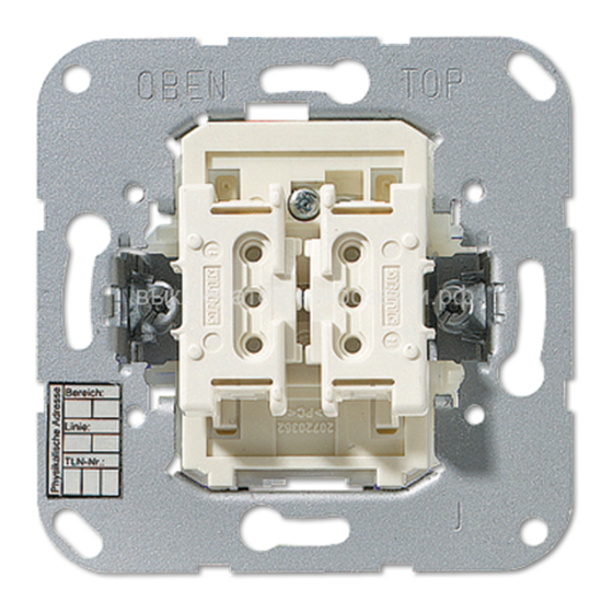
Product documentation
Push-button BCU
Art.-No.: 4071.0x LED, 4072.0x LED
Push-button BCU IP44
Art.-No.: 8471.0x LED W, 8472.0x LED W
ALBRECHT JUNG GMBH & CO. KG
Volmestraße 1
58579 Schalksmühle
Telefon: +49.23 55.8 06-0
Telefax: +49.23 55.8 06-2 04
kundencenter@jung.de
www.jung.de
Service Center
Issue: 10.05.2012
Kupferstr. 17-19
629x2y2z
44532 Lünen
Germany
Advertisement
Table of Contents


Need help?
Do you have a question about the KNX 4071.0 LED Series and is the answer not in the manual?
Questions and answers