Advertisement
Advertisement
Table of Contents

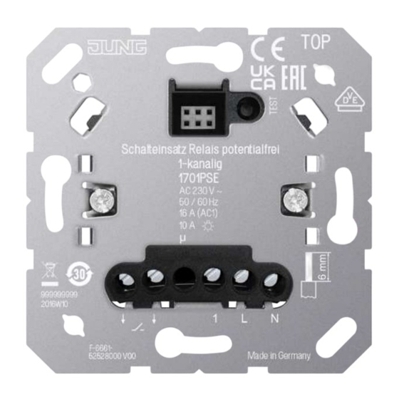
Summary of Contents for Jung 1701PSE
- Page 1 Operating instructions Relay switch insert with floating contact, 1-channel Art. no. 1701PSE ALBRECHT JUNG GMBH & CO. KG Volmestraße 1 58579 Schalksmühle GERMANY Telefon: +49 2355 806-0 Telefax: +49 2355 806-204 kundencenter@jung.de 23.08.2022 82406003 J0082406003 www.jung.de...
- Page 2 Relay switch insert with floating contact, 1-channel Table of Contents Safety instructions ...................... 3 Intended use ........................ 3 Product characteristics ...................... 3 Operation .......................... 3 Information for electrically skilled persons ................ 4 Technical data ........................ 6 Warranty.......................... 7 82406003 2 / 7 23.08.2022 J0082406003...
- Page 3 Control of electric underfloor heating systems and electrothermal valve drives in combination with a room thermostat cover or KNX RF push-button – Operation with suitable cover from the systems LB management, JUNG HOME, eNet and KNX RF – Mounting in appliance box with dimensions according to DIN 49073...
- Page 4 Relay switch insert with floating contact, 1-channel The time function cannot be restarted by pressing again. Information for electrically skilled persons DANGER! Mortal danger of electric shock. Disconnect the device. Cover up live parts. Connecting and fitting the device Image 1: Connection diagram with optional extensions Image 2: Terminal-specific cable cross-section 82406003 4 / 7...
- Page 5 Relay switch insert with floating contact, 1-channel ■ Connect the switch insert (2) according to the connection diagram (see figure 1). Note clampable cable cross-sections (see figure 2). ■ If multiple circuit breakers supply dangerous voltages to the device or load, couple the circuit breakers or label them with a warning, to ensure disconnec- tion is guaranteed.
- Page 6 Relay switch insert with floating contact, 1-channel Image 3: Connection diagram in combination with a room thermostat cover or KNX RF push-button Switching contact for switching to cooling mode Electric underfloor heating system (max. 16 A) or electrothermal valve drives If 230 V is applied to extension input 1, cooling mode is active. Technical data Rated voltage AC 230 V ~...
- Page 7 2-wire, push-button unlimited 3-wire extension, rotary extension Warranty The warranty is provided in accordance with statutory requirements via the specialist trade. ALBRECHT JUNG GMBH & CO. KG Volmestraße 1 58579 Schalksmühle GERMANY Telefon: +49 2355 806-0 Telefax: +49 2355 806-204 kundencenter@jung.de...


Need help?
Do you have a question about the 1701PSE and is the answer not in the manual?
Questions and answers