Table of Contents
Advertisement
Quick Links
Advertisement
Table of Contents

Related Manuals for Jung 1704ESE


Summary of Contents for Jung 1704ESE
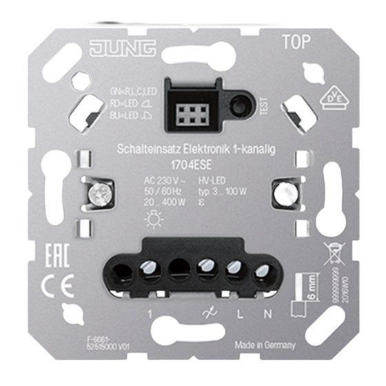
- Page 1 Operating instructions Electronic switch insert 1-channel Art. no. 1704ESE ALBRECHT JUNG GMBH & CO. KG Volmestraße 1 58579 Schalksmühle GERMANY Telefon: +49 2355 806-0 Telefax: +49 2355 806-204 kundencenter@jung.de 25.08.2022 82400533 J0082400533 www.jung.de...
-
Page 2: Table Of Contents
Electronic switch insert 1-channel Table of Contents Safety instructions ...................... 3 Intended use ........................ 3 Product characteristics ...................... 3 Operation .......................... 4 Information for electrically skilled persons ................ 4 Mounting and electrical connection................ 4 Commissioning ...................... 7 Technical data ........................ 8 Troubleshooting ........................ 9 Accessories ........................ 10 Warranty.......................... 10 82400533 2 / 11 25.08.2022... -
Page 3: Safety Instructions
This manual is an integral part of the product, and must remain with the end cus- tomer. Intended use – Operation with suitable cover from the systems LB management, JUNG HOME, eNet and KNX RF – Mounting in appliance box with dimensions according to DIN 49073 Operation with neutral conductor –... -
Page 4: Operation
Electronic switch insert 1-channel – Electronic over-temperature protection – Enables silent switching compared with a relay or room thermostat insert Flickering of the connected lamps through centralised pulses from the power stations. This does not represent any defect in the device. Operation with neutral conductor –... - Page 5 Electronic switch insert 1-channel Image 1: Connection diagram with optional extensions Button Test Display LED and connection socket for cover 2-wire extension 3-wire extension Push-button, NO contact Connect 600 Watt LED lamps or compact fluorescent lamps at most per 16 ampere circuit breaker. When connecting transformers, observe the data of the transformer manufacturer.
- Page 6 Electronic switch insert 1-channel There could be an increased likelihood of unsuitable combinations of LED lamp and switch insert. Lit push-buttons must have a separate N terminal. Image 2: Clampable conductor cross-section The load can be switched by briefly pressing the Test button. Connecting and mounting the device as a room thermostat (see figure 3) Recommended installation height: 1.50 m.
-
Page 7: Commissioning
Electronic switch insert 1-channel Commissioning Operation with neutral conductor The device is powered via the phase conductor and neutral conductor. There is no leading edge phase control or trailing edge phase control. Setting an operating mode is not necessary. Therefore, button Test (1) and LED (2) have no function for com- missioning. -
Page 8: Technical Data
Electronic switch insert 1-channel Image 4: Assignment of LED colour for the operating mode ■ Keep pressing button Test (1) for less than 1 second, until the necessary oper- ating mode is selected. The LED (2) lights up in the colour of the selected operating mode (see figure 4). -
Page 9: Troubleshooting
Electronic switch insert 1-channel ohmic and compact fl lamp. typ. 3 ... 100 W Power specifications including transformer dissipation. Operate inductive transformers with at least 85% nominal load. Operation without neutral conductor in operating mode R,L,C,LED: Ohmic-in- ductive mixed load: maximum 50% proportion of ohmic load. Otherwise, an in- correct measurement is possible. -
Page 10: Accessories
Electronic switch insert 1-channel The device switches the load off briefly and then on again. Cause: Short-circuit protection has tripped but now there is no longer a fault. The device has switched off and cannot be switched on again Cause 1: Overheating protection has tripped. Disconnect device from mains by switching off circuit breaker. - Page 11 Electronic switch insert 1-channel ALBRECHT JUNG GMBH & CO. KG Volmestraße 1 58579 Schalksmühle GERMANY Telefon: +49 2355 806-0 Telefax: +49 2355 806-204 kundencenter@jung.de www.jung.de 82400533 11 / 11 25.08.2022 J0082400533...
Need help?
Do you have a question about the 1704ESE and is the answer not in the manual?
Questions and answers