Banner SureCross Q45 Quick Start Manual
Wireless sensor-button/light
Hide thumbs
Also See for SureCross Q45:
- Quick start manual (2 pages) ,
- Setup manual (12 pages) ,
- Quick start manual (2 pages)
Table of Contents
Advertisement
Quick Links
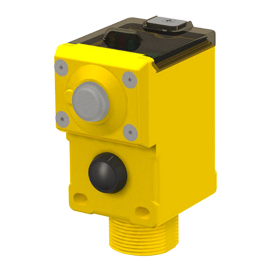
SureCross Wireless Q45 Sensor - Button/Light
SureCross® Wireless Q45 Sensors combine the best of Banner's flexible Q45 sensor family with its reliable, field-proven, SureCross
wireless architecture to solve new classes of applications limited only by the user's imagination. Containing a variety of sensor models, a
radio, and internal battery supply, this product line is truly plug and play.
Storage Mode for the Wireless Q45 Sensors
While in storage mode, the Wireless Q45 Sensor's radio does not operate. All Wireless Q45 Sensors ship from the factory in storage
mode to conserve the battery. To wake the device, press and hold the button for five seconds. To put any Wireless Q45 Sensor into
storage mode, press and hold the button for five seconds. The Wireless Q45 Sensor is in storage mode when the LEDs stop blinking.
Button, LEDs, and DIP Switches (Button with Light Model)
3
2
1
DIP Switch Settings
After making any changes to any DIP switch position, reboot the Wireless Q45 Sensor by triple-clicking the button, waiting a second, then
double-clicking the button. You may also reboot the device by removing the battery pack, then re-installing it.
As shown in the image above, the DIP switches are in the OFF position. To turn a DIP switch on, push the switch toward the battery
pack. DIP switches one through four are numbered from left to right as shown above.
Description
Reserved (keep in OFF position)
Buy: www.ValinOnline.com | Phone 844-385-3099 | Email: CustomerService@valin.com
The Wireless Q45 Sensor with Button and Light as a wireless node with independently controlled
push button input and a two-color LED indicator light. The push button can be configured with
DIP switches for either toggle or momentary operation; the red and green LED indicator lights
outputs can be configured for solid or flashing operation.
Available Models
• DX80N2Q45BL-RG
WARNING: Not To Be Used for Personnel Protection
Never use this device as a sensing device for personnel pro-
tection. Doing so could lead to serious injury or death. This
device does not include the self-checking redundant circuitry nec-
essary to allow its use in personnel safety applications. A sensor
failure or malfunction can cause either an energized or de-ener-
gized sensor output condition.
1
Button
2
Green LED (flashing) indicates a good radio link with the Gateway.
4
3
Red LED (flashing) indicates a radio link error with the Gateway.
5
4
Amber LED indicates when input 1 is active. The LED is active at power up and
disabled after 15 minutes to conserve power. To enable the LED for another 15
minutes, press button once. To disable the LED, press the button 5 times.
5
DIP Switches
DIP Switches
1
2
OFF *
3
4
Advertisement
Table of Contents

Subscribe to Our Youtube Channel
Related Manuals for Banner SureCross Q45


Summary of Contents for Banner SureCross Q45
- Page 1 SureCross Wireless Q45 Sensor - Button/Light SureCross® Wireless Q45 Sensors combine the best of Banner’s flexible Q45 sensor family with its reliable, field-proven, SureCross wireless architecture to solve new classes of applications limited only by the user’s imagination. Containing a variety of sensor models, a radio, and internal battery supply, this product line is truly plug and play.
- Page 2 Replacement battery model number: BWA-BATT-006. For pricing and availability, contact Banner Engineering. 1 The light consumes most of the sensor's power. If the light remains off most of the time, the batteries will last much longer. In flashing mode, the light can be on for up to one year on a pair of batteries.
- Page 3 SureCross Wireless Q45 Sensor - Button/Light Bind the Q45s to the Gateway and Assign the Node Address Before beginning the binding procedure, apply power to all the devices. 1. Enter binding mode on the Gateway. For -B2Q board modules, triple-click the button. For -Q and -QC models, triple-click button 2.
- Page 4 SureCross Wireless Q45 Sensor - Button/Light • Connect the red tower light (brown) wire to the Gateway's DO1 terminal. • Connect the green tower light (black) wire to the Gateway's DO2 terminal. • Connect the tower light's ground (blue) wire to the Gateway's GND terminal. On the Wireless Q45 Sensor To configure the sensor for this call for parts application, use the default DIP switch settings (all set to the OFF position).
- Page 5 Banner Engineering Corp. warrants its products to be free from defects in material and workmanship for one year following the date of shipment. Banner Engineering Corp. will repair or replace, free of charge, any product of its manufacture which, at the time it is returned to the factory, is found to have been defective during the warranty period.
Need help?
Do you have a question about the SureCross Q45 and is the answer not in the manual?
Questions and answers