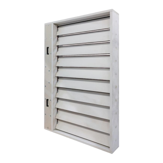
Mandik SEDM-L Manual
Smoke extraction damper/multi
Hide thumbs
Also See for SEDM-L:
- Manual (63 pages) ,
- Technical documentation manual (60 pages) ,
- Installation, operation, maintenance and service manual (66 pages)
Table of Contents
Advertisement
Quick Links
Advertisement
Table of Contents

Related Manuals for Mandik SEDM-L


Summary of Contents for Mandik SEDM-L
-
Page 2: Table Of Contents
These technical specifications state a row of manufactured sizes, main dimensions, design and range of use of multi-blade smoke and heat extraction dampers - multi SEDM-L (hereinafter only dampers). It is valid for production, design, ordering, delivery, storage, assembly, operation, maintenance and serviceability checks. -
Page 3: Description
EN 12101-8 • Certificate of Constancy of Properties No. 1391-CPR-2021/0009 • Performance declaration No. PM/SEDM-L/01/22/1 • Hygienic assessment of fire dampers - Report No. 1.6/pos/21/19b In a solid wall construction and on duct in a solid wall construction, th. - Page 4 In normal operation, the SEDM-L dampers remain closed. If necessary, in the event of a fire, the SEDM-L dampers in the affected fire section will open completely so that the smoke can be removed. When the smoke and heat removal dampers are activated, the dampers used for air supply in the affected section open.
-
Page 5: Design
Design with actuating mechanism Belimo actuators are used for dampers, series BEN, BEE, BE for 230V AC resp. 24 V AC/DC. After connection to the power supply voltage, the actuator moves the damper blades to the "OPEN" position or "CLOSED" (according to the corresponding connection, see wiring diagram). If the power supply is interrupted, the actuator stops at the current position. - Page 6 AC/DC 24 V AC/DC 24 V AC 230 V Power voltage 50/60Hz 50/60Hz 50/60Hz Power consumption - in operation - in the end position 0,1 W 0,3 W 0,4 W Dimensioning 6 VA (Imax 8,2 A @ 5 ms) 6,5 VA (Imax 8.2 A @ 5 ms) 7 VA (Imax 4 A @ 5 ms) Protection class Degree of protection...
- Page 7 AC/DC 24 V AC/DC 24 V AC 230 V Power voltage 50/60Hz 50/60Hz 50/60Hz Power consumption - in operation 2,5 W 3,5 W - in the end position 0,1 W 0,3 W 0,4 W Dimensioning 5 VA (Imax 8,2 A @ 5 ms) 5,5 VA (Imax 8.2 A @ 5 ms) 6 VA (Imax 4 A @ 5 ms) Protection class...
- Page 8 AC/DC 24 V AC 230 V Power voltage 50/60Hz 50/60Hz Power consumption - in operation 12 W - in the end position 0,5 W 0,5 W Dimensioning 18 VA (Imax 8,2 A @ 5 ms) 15 VA (Imax 7,9 A @ 5 ms) Protection class Degree of protection IP 54...
- Page 9 Design with actuating mechanism, communication and power supply device BKNE 230-24 Design with communication and power supply device BKNE 230-24 and with actuator BEN (BEE, BE)-ST for 24V. The BKNE 230-24 serves on the one hand as a decentralized network device for powering the actuator and on the other hand transmits the signal of the communication and control device BKSE 24-6.
- Page 10 Communication and supply device Power voltage AC 230V 50/60Hz Power consumption 10 W (including actuator) Dimensioning 19 VA (including actuator) Protection class Ambient operation temperature -30°C … +50°C Storage temperature -40°C … +80°C Connection - network cable 1 m without plug - drive 6-pin plug, 3-pin plug - terminal blocks...
- Page 11 Communication and control devices indicates operating condition and faults of dampers. These conditions can be signalled or transmitted to the higher-level control system via the auxiliary built-in contacts. Signals from individual BKNE 230-24 are evaluated separately. All BKNE 230-24 are controlled simultaneously.
-
Page 12: Dimensions, Weights
Dimensions... - Page 13 Detail X Detail Y...
- Page 15 0,0537 39,0 0,0682 40,7 0,0827 42,4 0,0972 44,3 0,1117 45,9 0,1262 47,6 0,1407 49,3 0,1552 51,0 0,1697 52,7 0,1842 54,8 0,1987 56,5 (15 N.m) 0,2132 59,8 0,2277 61,5 0,2422 63,2 0,2567 64,9 0,2712 66,9 0,2857 68,6 0,3002 70,3 0,3147 72,0 0,3292 73,7 0,3437...
- Page 16 0,1425 74,1 0,1810 76,8 0,2195 79,6 (15 N.m) 0,2580 82,6 0,2965 85,3 0,3350 89,7 0,3735 92,4 0,4120 95,2 0,4505 99,1 0,4890 102,4 0,5275 105,2 (25 N.m) 0,5660 108,3 0,6045 111,1 0,6430 113,9 0,6815 116,6 0,7200 120,0 0,7585 122,7 0,7970 125,5 0,8355 128,2 (40 N.m)
- Page 17 0,2313 108,1 0,2938 111,9 0,3563 115,7 0,4188 121,4 0,4813 126,4 (25 N.m) 0,5438 130,2 0,6063 134,0 0,6688 138,4 0,7313 142,2 0,7938 146,6 0,8563 150,4 0,9188 154,2 0,9813 158,0 1,0438 161,8 1,1063 165,6 (40 N.m) 1,1688 170,0 1,2313 173,8 1,2938 177,6 1,3563 181,4 1,4188...
-
Page 18: Placement And Assembly
Position: Damper housing Blade stop Handling inserts (2pc)* Blades Board - not included** * Included in package of larger dimensions SEDM-L. Forks ** Construction board thickness min. 25 mm. - Page 20 Detail X Detail Y Detail Y Detail X Position: SEDM-L Flange...
- Page 21 Position: SEDM-L Flange Blades * Fix in all holes, around the perimeter of the flange. Screw UNI 4x30 mm* - included in the flange package...
- Page 22 Spacer ring - included in the grille package Retaining ring - included in the grille package Rivet nuts - mounted on the flange from the factory Position: SEDM-L Pre-drilled holes Handrail - part of SEDM-L Screw 5x50 mm - part of SEDM-L...
- Page 23 Distance 75 mm between the damper and the structure (wall/ceiling). ● When installing SEDM-L (smaller dimensions), which is not equipped with transport spacers ● and corners, the Blades must be in the “CLOSED” position. The damper body must not be deformed during installation and fire stopping.
-
Page 25: Statement Of Installations
Mortar or gypsum EIS 90 Ablative Coated Batt EIS 120 Ablative Coated Batt EIS 120... - Page 26 This is the recommended size Position: SEDM-L Solid wall construction British gypsum thistle bond 60 (or equivalent can by used) minimum density 670 kg/m³) Flange...
- Page 27 6.5. and 6.6. For connection following duct see. chapter 7. = min. 30 mm, max. 400 mm Position: SEDM-L Solid wall construction Ablative Coated Batt (e.g. Firestop Board HILTI CFS-CT B 1S 140/50 - min. density 140 kg/m...
- Page 28 6.5. and 6.6. For connection following duct see. chapter 7. = min. 30 mm, max. 400 mm Position: SEDM-L Gypsum wall construction Ablative Coated Batt (e.g. Firestop Board HILTI CFS-CT B 1S 140/50 - min. density 140 kg/m...
- Page 29 Bolts and nuts shall not prevent free rotation on the blades. Examples of anchors to the fire dividing construction see. chapter 6.5. and 6.6. Position: SEDM-L Solid / gypsum wall construction British gypsum thistle bond 60 (or equivalent can by used) minimum density 670 kg/m³) Ablative Coated Batt (e.g.
- Page 30 ≥ 100 When installing a flange, overplating strip is not installed. Position: SEDM-L Solid / gypsum wall construction British gypsum thistle bond 60 (or equivalent can by used) minimum density 670 kg/m³) Ablative Coated Batt (e.g.
- Page 31 ≥ 100 When installing a flange, over- plating strip is not installed. Position: SEDM-L Solid wall construction British gypsum thistle bond 60 (or equivalent can by used) minimum density 670 kg/m³) Overplating strip (e.g. Supalux-S, th. 15 mm)** Screw UNI 4x40 mm (span 200 to 250 mm) Spacing strip (e.g.
- Page 32 ≥ 100 Examples of anchors to the fire dividing construction see. chapter 6.5. and 6.6. Position: SEDM-L Solid wall construction Ablative Coated Batt (e.g. Firestop Board HILTI CFS-CT B 1S 140/50 - min. density 140 kg/m + Firestop acrylic sealant HILTI CFS-S ACR or equivalent) Fire stop coating thickness 1 mm (e.g.
- Page 33 Bolts and nuts shall not prevent free rotation on the blades. When installing a flange, overplating strip is not installed. Position: SEDM-L Gypsum wall construction Mineral wool (type depending on the type of construction) Steel profile for plasterboard constructions Ablative Coated Batt (e.g. Firestop Board HILTI CFS-CT B 1S 140/50 - min.
- Page 34 When installing a flange, overplating strip is not installed. Examples of anchors to the fire dividing construction see. chapter 6.5. and 6.6. Position: SEDM-L Solid wall construction British gypsum thistle bond 60 (or equivalent can by used) minimum density 670 kg/m³) Ablative Coated Batt (e.g.
- Page 35 When installing a flange, overplating strip is not installed. Examples of anchors to the fire dividing construction see. chapter 6.5. and 6.6. Position: SEDM-L Gypsum wall construction Mineral wool (type depending on the type of construction) Steel profile for plasterboard constructions Ablative Coated Batt (e.g.
- Page 36 When installing a flange, over- plating strip is not installed. ≥ 100 Position: SEDM-L Solid / gypsum wall construction British gypsum thistle bond 60 (or equivalent can by used) minimum density 670 kg/m³) Ablative Coated Batt (e.g.
-
Page 37: Suspension System
The dampers and duct must be suspended separately. Position: SEDM-L Duct Fixing profile with threaded rod see. chapter 6.4. The dampers and duct must be suspended separately. Position: SEDM-L Duct Damper can be put at the end of a duct as an option. - Page 38 The dampers must be suspended using threaded rods and mounting profiles. Their dimensioning depends on the damper's weight. The dampers and duct must be suspended separately. The connected duct must be suspended in such a way that the transfer of all loads from the adjoining ventilation duct to the damper body is completely excluded.
- Page 39 50 Position: SEDM-L Threaded rod M8 - M20 Support HILTI MQ-41 (or MQ-41/3 or equivalent) Bored plate HILTI MQZ-L or equivalent Washer for M8 - M20 Nut M8 - M20...
- Page 40 Fixing SEDM-L to the solid wall construction with Ablative Coated Batt system Full drawing of bracket, see on page 42. Position: Solid wall construction SEDM-L Ablative Coated Batt Fixing element/steel bracket for connecting damper to the wall (optional accessories MANDIK, a.s. or sheet metal min.
- Page 41 Fixing SEDM-L to the gypsum wall construction with Ablative Coated Batt system Position: Gypsum wall construction SEDM-L Full drawing of bracket, see on page 42. Ablative Coated Batt Fixing element/steel bracket for connecting damper to the wall (optional accessories MANDIK, a.s. or sheet metal min.
- Page 42 Fixing element/steel bracket for connecting damper to the wall Position: Fixing element/steel bracket for connecting damper to the wall (optional accessories MANDIK, a.s. or sheet metal min. thickness 2 mm and min. width 60 mm) Installation hols M8 bolt assemply:...
-
Page 43: Duct Connection
Position: SEDM-L Connecting air duct MULTI Flange of SEDM-L Flange of duct M8 bolt assemply (bolt M8x20 mm, 2 pcs large washer M8, nut M8) * Ceramic self-adhesive tape (FJ 120 Pyrosil B 170-250 kg/m - Tremco-illbruck) or equivalent Lock washers... - Page 44 5 mm, length min. 60 mm - acc.to min. thickness Ø protective cladding boards (th. 30 mm - see. Pos. 2), max. spacing 250 mm SUPALUX / PROMATECT-L500 - th. min 30 mm Insulation duct MULTI acc. to EN 1366-8 Part of SEDM-L...
-
Page 45: Pressure Loss
Pressure loss calculation [Pa] presure loss [m.s ] air flow speed in nominal damper section [kg.m ] air density coefficient of local pressure loss for the nominal damper section (see Chapter. 9) Determination of pressure loss by using diagram = 1,2 kg.m... - Page 46 0,658 0,586 0,554 0,535 0,523 0,515 0,509 0,504 0,500 0,637 0,568 0,536 0,518 0,507 0,499 0,493 0,488 0,484 0,624 0,556 0,525 0,508 0,496 0,488 0,482 0,478 0,474 0,614 0,548 0,517 0,500 0,489 0,481 0,475 0,471 0,467 0,608 0,542 0,512 0,494 0,483 0,476 0,470...
- Page 47 1,250 1,114 1,052 1,017 0,994 0,978 0,967 0,958 0,950 1,210 1,079 1,019 0,985 0,963 0,947 0,936 0,927 0,920 1,185 1,056 0,998 0,964 0,943 0,928 0,916 0,908 0,901 1,167 1,041 0,983 0,950 0,929 0,914 0,903 0,894 0,888 1,154 1,029 0,972 0,939 0,918 0,904 0,893...
- Page 48 1,151 1,026 0,969 0,937 0,916 0,901 0,890 0,882 0,875 1,115 0,994 0,939 0,907 0,887 0,873 0,862 0,854 0,848 1,091 0,973 0,919 0,888 0,868 0,854 0,844 0,836 0,830 1,075 0,958 0,905 0,875 0,855 0,842 0,832 0,824 0,818 1,063 0,948 0,895 0,865 0,846 0,832 0,822...
- Page 49 3,994 3,680 3,537 3,456 3,403 3,366 3,339 3,318 3,301 3,903 3,599 3,460 3,381 3,330 3,294 3,268 3,247 3,231 3,844 3,546 3,411 3,333 3,283 3,248 3,222 3,202 3,187 3,803 3,510 3,376 3,300 3,251 3,216 3,191 3,171 3,156 3,773 3,483 3,351 3,276 3,227 3,193 3,168...
-
Page 50: Noise Data
Level of acoustic output corrected with filter A... -
Page 54: Material
Damper bodies and blades are made of asbestos-free fire-resistant mineral fibre boards. Damper bodies and blades can be coated with Promat 2000 anti-moisture coating or Promat-SR anti-aggressive coating. The connecting material is galvanised. According to the customer's request, a stainless-steel damper can be supplied. Specification of stainless-steel design - division of stainless-steel material: class A2 - food stainless-steel (AISI 304 - EN 17240) ●... -
Page 55: Logistic Terms
Dampers are delivered on special pallets. As standard, the dampers are wrapped in plastic foil for protection during transport and must not be used for long-term storage of the equipment . Changes in temperature during transport may cause condensation of water vapour inside the packaging and thereby condisitions may arise inside the packaging that are suitable for corrosion of materials used in the equipment (e.g. -
Page 56: Assembly
Damper installation, maintenance and serviceability checks may only be performed by personnel qualified for these activities, i.e. "AUTHORISED PERSONNEL". Additional training for these inspections, installation and repairs is performed by MANDÍK, a.s. and issues a "CERTIFICATE", which is valid for 5 years. Its extension is provided by a trained person directly from the trainer. -
Page 57: Entry Into Service And Revisions
Spare parts are only delivered on order. The data label is attached to the damper body. MANDÍK, a.s. Dobříšská 550, 267 24 Hostomice, Czech Republic DIMENSION: ACTUATING SYSTEM: WEIGHT (kg): YEAR/SER.NO.: MANUAL FIRE PROTEC. CLASS: TPM 146/20 Cert. No.: 1391-CPR-2021/0009, DoP: PM/SEDM-L/01/22/1 EN 12101-8:2011 1391... -
Page 58: Ordering Key
Smoke extraction damper Technical specifications - without flange and grille - flange over blades - flange over damper - flange and grille over blades** - flange and grille over damper** Design acc. to Tab. 19.1.1. Nominal size Type with actuating mechanism BEN, BEE, BE for 230V with actuating mechanism BEN, BEE, BE for 24V with actuating mechanism BEN (BEE)-SR for 24V .65***... - Page 59 MANDÍK, a.s. Dobříšská 550 26724 Hostomice Czech Republic Tel.: +420 311 706 706 E-Mail: mandik@mandik.cz www.mandik.com The producer reserves the right for innovations of the product. For actual product information see www.mandik.com...
Need help?
Do you have a question about the SEDM-L and is the answer not in the manual?
Questions and answers