Mandik SEDM-L Manual
Hide thumbs
Also See for SEDM-L:
- Manual (59 pages) ,
- Technical documentation manual (60 pages) ,
- Installation, operation, maintenance and service manual (66 pages)

Subscribe to Our Youtube Channel
Related Manuals for Mandik SEDM-L


Summary of Contents for Mandik SEDM-L
-
Page 2: Table Of Contents
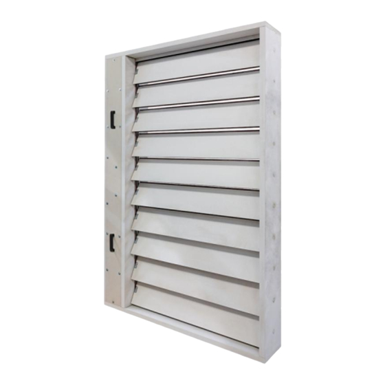
These technical conditions stipulate a number of manufactured sizes, main dimensions, design and range of use of multi-slat smoke and heat extraction dampers - multi SEDM-L (hereinafter only dampers). They're binding for production, design, ordering, delivery, storage, assembly, operation, maintenance and serviceability checks. - Page 3 In normal operation, the SEDM-L dampers remain closed. If necessary, in the event of a fire, the SEDM-L dampers in the affected fire section will open completely so that the smoke can be removed.
- Page 4 EN 12101-8 • Certificate of Constancy of Properties No. 1391-CPR-2021/0009 • Performance declaration No. PM/SEDM-L/01/22/1 • Hygienic assessment of fire dampers - Report No. 1.6/pos/21/19b In a solid wall construction and on duct in a solid wall construction, th.
- Page 5 Belimo actuators are used for dampers, series BEN, BEE, BE for 230V AC resp. 24 V AC/DC. After connection to the power supply voltage, the actuator moves the damper slats to the "OPEN" position or "CLOSED" (according to the corresponding connection, see wiring diagram). If the power supply is interrupted, the actuator stops at the current position.
- Page 6 AC/DC 24 V AC/DC 24 V AC 230 V Power voltage 50/60Hz 50/60Hz 50/60Hz Power consumption - in operation - in the end position 0,1 W 0,3 W 0,4 W Dimensioning 6 VA (Imax 8,2 A @ 5 ms) 6,5 VA (Imax 8.2 A @ 5 ms) 7 VA (Imax 4 A @ 5 ms) Protection class Degree of protection...
- Page 7 AC/DC 24 V AC/DC 24 V AC 230 V Power voltage 50/60Hz 50/60Hz 50/60Hz Power consumption - in operation 2,5 W 3,5 W - in the end position 0,1 W 0,3 W 0,4 W Dimensioning 5 VA (Imax 8,2 A @ 5 ms) 5,5 VA (Imax 8.2 A @ 5 ms) 6 VA (Imax 4 A @ 5 ms) Protection class...
- Page 8 AC/DC 24 V AC 230 V Power voltage 50/60Hz 50/60Hz Power consumption - in operation 12 W - in the end position 0,5 W 0,5 W Dimensioning 18 VA (Imax 8,2 A @ 5 ms) 15 VA (Imax 7,9 A @ 5 ms) Protection class Degree of protection IP 54...
-
Page 9: Design
Design with communication and power supply device BKNE 230-24 and with actuator BEN (BEE, BE)-ST for 24V. The BKNE 230-24 serves on the one hand as a decentralized network device for powering the actuator and on the other hand transmits the signal of the communication and control device BKSE 24-6. It simplifies electrical installation and connection of dampers. - Page 10 Power voltage AC 230V 50/60Hz Power consumption 10 W (including actuator) Dimensioning 19 VA (including actuator) Protection class Ambient operation temperature -30°C … +50°C Storage temperature -40°C … +80°C Connection - network cable 1 m without plug - drive 6-pin plug, 3-pin plug - terminal blocks screw terminals for 2x1.5 mm conductor...
- Page 11 indicates operating condition and faults of flue dampers. These conditions can be signalled or transmitted to the higher-level control system via the auxiliary built-in contacts. Signals from individual BKNE 230-24 are evaluated separately. All BKNE 230-24 are controlled simultaneously. A maximum of 6 BKNE 230-24 can be connected to the BKSE 24-6. Damper control is ensured with a simple 2-wire line.
- Page 13 Detail X Detail Y...
- Page 15 0,0537 39,0 0,0682 40,7 0,0827 42,4 0,0972 44,3 0,1117 45,9 0,1262 47,6 0,1407 49,3 0,1552 51,0 0,1697 52,7 0,1842 54,8 0,1987 56,5 (15 N.m) 0,2132 59,8 0,2277 61,5 0,2422 63,2 0,2567 64,9 0,2712 66,9 0,2857 68,6 0,3002 70,3 0,3147 72,0 0,3292 73,7 0,3437...
- Page 16 0,1425 74,1 0,1810 76,8 0,2195 79,6 (15 N.m) 0,2580 82,6 0,2965 85,3 0,3350 89,7 0,3735 92,4 0,4120 95,2 0,4505 99,1 0,4890 102,4 0,5275 105,2 (25 N.m) 0,5660 108,3 0,6045 111,1 0,6430 113,9 0,6815 116,6 0,7200 120,0 0,7585 122,7 0,7970 125,5 0,8355 128,2 (40 N.m)
- Page 17 0,2313 108,1 0,2938 111,9 0,3563 115,7 0,4188 121,4 0,4813 126,4 (25 N.m) 0,5438 130,2 0,6063 134,0 0,6688 138,4 0,7313 142,2 0,7938 146,6 0,8563 150,4 0,9188 154,2 0,9813 158,0 1,0438 161,8 1,1063 165,6 (40 N.m) 1,1688 170,0 1,2313 173,8 1,2938 177,6 1,3563 181,4 1,4188...
- Page 18 They're designed for installation in smoke and heat removal duct according to EN1366-8. ● They're suitable for installation in a vertical position, with the slat axis horizontal. ● Dampers and duct must be suspended separately. The connected piping must be suspended in such ●...
- Page 20 Detail X Detail Y Detail Y Detail X Position: SEDM-L Flange...
- Page 21 Position: SEDM-L Flange Slats Universal screw 4x30 (holes around the perimeter of the flange)
- Page 22 Position: Flange Grille Screw M6x20 (BN 4825) Spacer ring Retaining ring Rivet nuts Position: SEDM-L Pre-drilled holes Handrail Screw 5x50...
- Page 23 Distance 75 mm between the damper and the structure (wall/ceiling). ● When installing SEDM-L (smaller dimensions), which is not equipped with transport spacers ● and corners, the sheets must be in the “CLOSED” position. The damper body must not be deformed during installation.
- Page 25 Mortar or gypsum EIS 90 Weichschott / Ablative Coated Batt EIS 120 Weichschott / Ablative Coated Batt EIS 120...
- Page 26 This is the recommended size Position: SEDM-L Solid wall / shaft construction Mortar or gypsum Flange Grille...
- Page 27 Hilti CFS-CT * Fire resistant insulation and fire resistant board can be replaced by another approved fire sealing system for damper installation with equivalent material properties. Position: SEDM-L Solid wall / shaft construction Fire board Fire coating th. 1 mm Flange...
- Page 28 * Fire resistant insulation and fire resistant board can be replaced by another approved fire sealing system for damper installation with equivalent material properties. Position: SEDM-L Gypsum wall / shaft construction Mineral wool (type depending on the type of construction) Steel profile for plasterboard constructions Fire board Fire coating th.
- Page 29 When installing a flange, overplating strip is not installed. Bolts and nuts shall not prevent free rotation on the blades. Position: SEDM-L Solid wall construction Mortar or gypsum Overplating strip (e.g. Promatect-H, th. 15 mm) ** Screw 4x40 (span 200 to 250 mm) Spacing strip (e.g.
- Page 30 Bolts and nuts shall not prevent free rotation on the blades. When installing a flange, overplating strip is not installed. Position: SEDM-L Solid wall construction Fire board Fire coating th. 1 mm Overplating strip (e.g. Promatect-H, th. 15 mm) ** Screw 4x40 (span 200 to 250 mm) Spacing strip (e.g.
- Page 31 Bolts and nuts shall not prevent free rotation on the blades. When installing a flange, overplating strip is not installed. Position: SEDM-L Gypsum wall construction Mineral wool (type depending on the type of construction) Steel profile for plasterboard constructions Fire board Fire coating th.
- Page 32 ≥ 100 When installing a flange, overplating strip is not installed. Position: SEDM-L Solid wall construction Mortar or gypsum Overplating strip (e.g. Promatect-H, th. 15 mm) * Screw 4x40 (span 200 to 250 mm) Spacing strip (e.g. Promatect-H, th. 10 mm, width 40 to 50 mm)
- Page 33 When installing a flange, overplating strip is not installed. Position: SEDM-L Solid wall construction Fire board Fire coating th. 1 mm Overplating strip (e.g. Promatect-H, th. 15 mm) * Screw 4x40 (span 200 to 250 mm) Spacing strip (e.g.
- Page 34 When installing a flange, overplating strip is not installed. Position: SEDM-L Gypsum wall construction Mineral wool (type depending on the type of construction) Steel profile for plasterboard constructions Fire board Fire coating th.
- Page 35 When installing a flange, overplating strip is not installed. Bolts and nuts shall not prevent free rotation on the slats. Position: SEDM-L Solid wall construction Mortar or gypsum Overplating strip (e.g. Promatect-H, th. 15 mm) ** Screw 4x40 (span 200 to 250 mm) Spacing strip (e.g.
- Page 36 Bolts and nuts shall not prevent free rotation on the blades. When installing a flange, overplating strip is not installed. Position: SEDM-L Solid wall construction Fire board Fire coating th. 1 mm Overplating strip (e.g. Promatect-H, th. 15 mm) ** Screw 4x40 (span 200 to 250 mm) Spacing strip (e.g.
- Page 37 Bolts and nuts shall not prevent free rotation on the blades. When installing a flange, overplating strip is not installed. Position: SEDM-L Gypsum wall construction Mineral wool (type depending on the type of construction) Steel profile for plasterboard constructions Fire board Fire coating th.
- Page 38 When installing a flange, overplating strip is not installed. Bolts and nuts shall not prevent free rotation on the slats. Position: SEDM-L Solid wall construction Mortar or gypsum Overplating strip (e.g. Promatect-H, th. 15 mm) ** Screw 4x40 (span 200 to 250 mm) Spacing strip (e.g.
- Page 39 Bolts and nuts shall not prevent free rotation on the blades. When installing a flange, overplating strip is not installed. Position: SEDM-L Solid wall construction Fire board Fire coating th. 1 mm Overplating strip (e.g. Promatect-H, th. 15 mm) ** Screw 4x40 (span 200 to 250 mm) Spacing strip (e.g.
- Page 40 Bolts and nuts shall not prevent free rotation on the When installing a flange, overplating strip is not installed. Position: SEDM-L Gypsum wall construction Mineral wool (type depending on the type of construction) Steel profile for plasterboard constructions Fire board Fire coating th.
- Page 41 When installing a flange, overplating strip is not installed. ≥ 100 Position: SEDM-L Solid wall construction Mortar or gypsum Overplating strip (e.g. Promatect-H, th. 15 mm) * Screw 4x40 (span 200 to 250 mm) Spacing strip (e.g. Promatect-H, th. 10 mm, width 40 to 50 mm)
- Page 42 When installing a flange, overplating strip is not installed. Position: SEDM-L Solid wall construction Fire board Fire coating th. 1 mm Overplating strip (e.g. Promatect-H, th. 15 mm) * Screw 4x40 (span 200 to 250 mm) Spacing strip (e.g.
- Page 43 When installing a flange, overplating strip is not installed. Position: SEDM-L Gypsum wall construction Mineral wool (type depending on the type of construction) Steel profile for plasterboard constructions Fire board Fire coating th.
- Page 44 Mounting to the ceiling wall Position: ² Threaded rod M8 – M20 36,6 Washer 84,3 Coupling Nut Anchor Hinge plate - min. thickness 10 mm Concrete screw tested for fire resistance R30-R90, max. Tension up to 0.75 KN (length 35 mm)
- Page 45 Fixing SEDM-L to the solid wall construction with Weichschott / Ablative Coated Batt system Position: Solid wall construction SEDM-L Weichschott / Ablative Coated Batt Fixing element/steel holder for connecting damper to the wall (recommended type of anchor) Screws and nuts must not impede the free rotation of slats.
- Page 46 Fixing SEDM-L to the gypsum wall construction with Weichschott / Ablative Coated Batt system Position: Gypsum wall construction SEDM-L Weichschott / Ablative Coated Batt Fixing element/steel holder for connecting damper to the wall (recommended type) Screw with hexagon head Screws and nuts must not impede the free rotation of slats.
- Page 47 Threaded rods longer than 1.5 m must be protected by fire insulation. Fastening threaded rods to the ceiling structure – see Fig. 41 Position: SEDM-L Air duct MULTI (tested according to EN1366-8) Connecting strips according to instructions from smoke extracting duct manufacturers.(e.g. Promatect-H)** All contact surfaces must be glued (e.g.
- Page 48 Position: SEDM-L Connecting air duct MULTI Connecting strap Examples of materials used: Position: SEDM-L Connecting air duct MULTI Example of materials used: Solid wall construction Calcium silicate boards, min. density 500 kg/m , min. th. 30 mm Connecting strap (E.g. Promatect-L500, Promatect-MST, Promatect-H) Mineral wool Stone wool, min.
-
Page 49: Pressure Loss
Pressure loss calculation [Pa] presure loss [m.s ] air flow speed in nominal damper section [kg.m ] air density coefficient of local pressure loss for the nominal damper section (see Chapter. 9) Determination of pressure loss by using diagram = 1,2 kg.m... - Page 50 0,658 0,586 0,554 0,535 0,523 0,515 0,509 0,504 0,500 0,637 0,568 0,536 0,518 0,507 0,499 0,493 0,488 0,484 0,624 0,556 0,525 0,508 0,496 0,488 0,482 0,478 0,474 0,614 0,548 0,517 0,500 0,489 0,481 0,475 0,471 0,467 0,608 0,542 0,512 0,494 0,483 0,476 0,470...
- Page 51 1,250 1,114 1,052 1,017 0,994 0,978 0,967 0,958 0,950 1,210 1,079 1,019 0,985 0,963 0,947 0,936 0,927 0,920 1,185 1,056 0,998 0,964 0,943 0,928 0,916 0,908 0,901 1,167 1,041 0,983 0,950 0,929 0,914 0,903 0,894 0,888 1,154 1,029 0,972 0,939 0,918 0,904 0,893...
- Page 52 1,151 1,026 0,969 0,937 0,916 0,901 0,890 0,882 0,875 1,115 0,994 0,939 0,907 0,887 0,873 0,862 0,854 0,848 1,091 0,973 0,919 0,888 0,868 0,854 0,844 0,836 0,830 1,075 0,958 0,905 0,875 0,855 0,842 0,832 0,824 0,818 1,063 0,948 0,895 0,865 0,846 0,832 0,822...
- Page 53 3,994 3,680 3,537 3,456 3,403 3,366 3,339 3,318 3,301 3,903 3,599 3,460 3,381 3,330 3,294 3,268 3,247 3,231 3,844 3,546 3,411 3,333 3,283 3,248 3,222 3,202 3,187 3,803 3,510 3,376 3,300 3,251 3,216 3,191 3,171 3,156 3,773 3,483 3,351 3,276 3,227 3,193 3,168...
- Page 54 Level of acoustic output corrected with filter A...
-
Page 58: Material
Damper bodies and slats are made of asbestos-free fire-resistant mineral fibre boards. Damper bodies and slats can be coated with Promat 2000 anti-moisture coating or Promat-SR anti-aggressive coating. The connecting material is galvanised. According to the customer's request, a stainless-steel damper can be supplied. Specification of stainless-steel design - division of stainless-steel material: class A2 - food stainless-steel (AISI 304 - EN 17240) ●... -
Page 59: Assembly
The scope of delivery includes a complete damper and delivery note. The manufacturer provides a 24-month warranty on dampers from the shipment date. The manufacturer’s warranty for SEDM-L dampers completely expires after any unprofessional handling by untrained workers (see chapter 16.1.) With the control device, disassembly of electrical elements, i.e. -
Page 60: Spare Parts
Drill two holes into the protection box (from outside to inside) and pull through field wiring cables (fire resistant cables) to connect actuator trailing lead. Protection box is made of calcium silicate plates. Use drill (drill size acc. To suit connecting cable Ø + 2 mm for seal up by mastic) and make two holes (see fig. - Page 61 Smoke extraction damper Technical specifications - without flange and grille - flange over slats - flange over damper - flange and grille over slats** - flange and grille over damper** Design acc. to Tab. 19.1.1. Nominal size Type with actuating mechanism BEN, BEE, BE for 230V with actuating mechanism BEN, BEE, BE for 24V with actuating mechanism BEN (BEE)-SR for 24V .65***...
- Page 62 The data label is attached to the damper body. MANDÍK, a.s. Dobříšská 550, 267 24 Hostomice, Czech Republic DIMENSION: ACTUATING SYSTEM: WEIGHT (kg): YEAR/SER.NO.: MANUAL FIRE PROTEC. CLASS: TPM 146/20 Cert. No.: 1391-CPR-2021/0009, DoP: PM/SEDM-L/01/22/1 EN 12101-8:2011 1391...
- Page 63 MANDÍK, a.s. Dobříšská 550 26724 Hostomice Czech Republic Tel.: +420 311 706 706 E-Mail: mandik@mandik.cz www.mandik.com The producer reserves the right for innovations of the product. For actual product information see www.mandik.com...
Need help?
Do you have a question about the SEDM-L and is the answer not in the manual?
Questions and answers