
Related Manuals for Sullair LS-25S


Summary of Contents for Sullair LS-25S
- Page 1 INDUSTRIAL ROTARY SCREW AIR COMPRESSOR LS---25S 200---350HP/150---261KW AND 24KT SUPERVISOR I OPERATOR’S MANUAL AND PARTS LIST Part Number 02250059---710 eSullair Corporation, 1994 Effective 11/94...
- Page 2 AIR CARE SEMINAR TRAINING Sullair Air Care Seminars are 3---day courses that provide hands---on instruction in the proper operation, maintenance and service of Sullair equipment. Individual seminars on Industrial compressors and compressor electrical systems are presented at regular intervals throughout the year at a dedicated training facility at Sullair’s corporate headquarters in Michigan City, Indiana.
-
Page 3: Table Of Contents
1.8 ELECTRICAL SHOCK 1.9 LIFTING 1.10 ENTRAPMENT Section 2 DESCRIPTION 2.1 INTRODUCTION 2.2 DESCRIPTION OF COMPONENTS 2.3 SULLAIR COMPRESSOR UNIT, FUNCTIONAL DESCRIPTION 2.4 COMPRESSOR COOLING AND LUBRICATION SYSTEM, FUNCTIONAL DESCRIPTION 2.5 COMPRESSOR DISCHARGE SYSTEM, FUNCTIONAL DESCRIPTION 2.6 CONTROL SYSTEM, FUNCTIONAL DESCRIPTION 2.7 AIR INLET SYSTEM, FUNCTIONAL DESCRIPTION... - Page 4 TABLE OF CONTENTS (CONTINUED) Section 5 PAGE OPERATION 5.1 GENERAL 5.2 PURPOSE OF CONTROLS 5.3 INITIAL START---UP PROCEDURE 5.4 SUBSEQUENT START---UP PROCEDURE 5.5 SHUTDOWN PROCEDURE Section 6 MAINTENANCE 6.1 GENERAL 6.2 DAILY OPERATION 6.3 MAINTENANCE AFTER INITIAL 50 HOURS OF OPERATION 6.4 MAINTENANCE EVERY 1000 HOURS 6.5 FLUID CHANGE 6.6 SEPARATOR MAINTENANCE...
- Page 5 TABLE OF CONTENTS (CONTINUED) Section 7 ILLUSTRATIONS AND PARTS LIST (Continued) 7.7 FLUID COOLING SYSTEM --- AIR---COOLED REMOTE COOLER (300---350HP/225---261K W) 7.8 FLUID COOLING SYSTEM --- WATER---COOLED (200---250HP/150---187K W) 7.9 FLUID COOLING SYSTEM --- WATER---COOLED (300---350HP/225---261K W) 7.10 COMPRESSOR DISCHARGE SYSTEM 7.11 SULLICON CONTROL 7.12 COMPRESSOR ACTUATOR 7.13 ELECTRO---PNEUMATIC CONTROL SYSTEM...
- Page 6 SAFETY 1.1 GENERAL 1926.302(b)(7) and/or any applicable Federal, Sullair Corporation and its subsidiaries designs State and Local codes, standards and regulations. and manufactures all of its products so they can be B. When the hose is to be used to supply a mani- operated safely.
- Page 7 Section 1 SAFETY C. DO NOT permit fluids, including air line anti--- E. Make sure all personnel are out of and/or clear of icer system antifreeze compound or fluid film to ac- the compressor prior to attempting to start or oper- cumulate on, under, or around acoustical material, ate it.
- Page 8 Section 1 SAFETY F. Wear goggles or a full face shield when adding helicopter must not be supported by the lifting bail antifreeze compound to air line anti---icer systems. but by slings instead. In any event, lift and/or han- dle only in full compliance with OSHA standards 29 G.
-
Page 9: Entrapment
Section 1 SAFETY 1.10 ENTRAPMENT A. If the compressor enclosure, if any, is large enough to hold a man and if it is necessary to enter it to perform service adjustments, inform other per- sonnel before doing so, or else secure and tag the access door in the open position to avoid the possi- bility of others closing and possibly latching the door with personnel inside. -
Page 10: Introduction
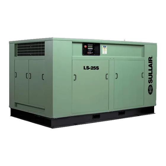
. The c omponents a nd assem - Both air---cooled and water---cooled versions have blies of the air compressor are clearly shown. The easily accessible items such as the fluid filters and Figure 2 ---1 Sullair Series LS ---25S 200HP/150KW Rotary Screw Compressor... -
Page 11: Sullair Compressor Unit, Functional Description
DESCRIPTION the compressor unit permitted in accordance with Sullair air compressors feature the Sullair compres- sor unit, a single---stage, positive displacement, lu- the terms of the warranty. Figure 2 ---2 Cooling and Lubrication System --- Typical (Water ---cooled) - Page 12 Section 2 DESCRIPTION Figure 2 ---3 Compressor Piping and /nstrument Diagram...
-
Page 13: Compressor Cooling And Lubrication System, Functional Description
Section 2 DESCRIPTION Fluid is injected into the compressor unit in large duced, causing the fluid stop valve to close and iso- quantities and mixes directly with the air as the ro- late the compressor unit from the cooling system. tors turn, compressing the air. - Page 14 Section 2 DESCRIPTION Figure 2 ---4 Compressor Discharge System --- Typical (Water ---cooled) The compressor is also equipped with high pres- WA R N I N G sure shutdown protection to shut down the com- pressor at 135 psig (9.3 bar). This prevents the re- lief valve from opening and dumping fluid under DO NOT remove caps, plugs, and/or other com- normal conditions.
-
Page 15: Control System, Functional Description
Section 2 DESCRIPTION Fluid is added to the sump via a capped fluid filler compressing only that amount of air which is being opening, located on the tank to prevent overfilling used. As air demand keeps dropping further, the of the sump. A sight glass enables the operator to spiral valve keeps opening more and more until all visually monitor the sump fluid level. - Page 16 Section 2 DESCRIPTION Figure 2 ---5A Control System Diagram (Start/Full Load)
- Page 17 Section 2 DESCRIPTION Figure 2 ---5B Control System Diagram (Modulation/Unload)
-
Page 18: Air Inlet System, Functional Description
Section 2 DESCRIPTION Figure 2 ---6 Air Inlet System 2.8 INSTRUMENTATION, FUNCTIONAL DESCRIP- ing in AUTOMATIC mode, press the EMERGENCY TION STOP button on the control panel. Refer to Figure 2---7. The Supervisor I control panel consists of displays for pressure, temperature and time, as well as a status message display. -
Page 19: Supervisor I Microcontroller Programming
Section 2 DESCRIPTION Figure 2 ---7 Supervisor I Control Panel the sump pressure at the various load and/or off--- ential of 10 psid (0.7 bar) is reached, the message load conditions. “SEPARATOR MAINT RQD” is displayed and the ∆P1 LED will flash. S The discharge temperature probe (T1) moni- tors the temperature of the air leaving the compres- S Oil filter differential pressure can be displayed... - Page 20 Section 2 DESCRIPTION PROGRAMMABLE PARAMETERS PARAMETER OPERATION LANGUAGE Press the cursor pad for 2 seconds to change to next language for the message display. Languages in or- der are: French, German, Italian, Spanish and En- glish. AUTOMATIC/MANUAL The controller default state is AUTOMATIC operation. If line pressure is adequate and/or the sump pressure is greater than 5 to 10 psig (0.3 to 0.7 bar), pressing the ON/OFF pad will put the control in STANDBY...
- Page 21 Section 2 DESCRIPTION SUPERVISOR I SPECIAL FUNCTION INPUTS PARAMETER OPERATION REMOTE STOP/START (J1/1---2) Closing this contact initiates the STOP mode. Open- ing this contact permits a compressor start if permis- sives are satisfied. Please note that AUTOMATIC/MA- NUAL mode characteristics are maintained even though remote STOP/START is used.
- Page 22 Section 2 DESCRIPTION SUPERVISOR OUTPUT RELAYS PARAMETERS OPERATION COMPRESSOR RUN Initiates starter controls and all auxiliary contacts that operate simultaneously with the main starter. Supervi- sor assumes compressor is running if contact is closed and P1 discharge pressure is at a satisfactory level.
- Page 23 Section 3 SPECIFICATIONS SULLAIR SERIES LS---25S SPECIFICATIONS (50 Hz) MODEL HP/KW COOLING CAPACITY LENGTH WIDTH HEIGHT (V) WEIGHT (VI) (ACFM/M /MIN) (IN/MM) (IN/MM) (IN/MM) (LB/KG) L (I) 200/150 Air 1000/28.3 134/3404 87/2210 76/1930 7845/3561 250/187 1200/33.9 134/3404 87/2210 76/1930 9395/4281 300/225 1500/41.7...
-
Page 24: Lubrication Guide
The fluid should be changed more frequently under se- Sullair encourages the user to participate in a fluid vere operating conditions, such as high ambient analysis program with the fluid suppliers. This... -
Page 25: Mounting Of Compressor
85_F (27_C to 29_C) water inlet temperature. ing excessive pressure drop is not created across the fan. Consult a Sullair office for assistance in util- Recommended water pressure range is 25 to 75 izing this heat. -
Page 26: Service Air Piping
Section 4 INSTALLATION Figure 4 ---1 Service Air Piping (Typical Installation) BLOCK AND BYPASS VALVES DO NOT install a water---cooled or an air---cooled/ WA R N I N G aftercooled compressor without adequate freeze protection where it will be exposed to temperature less than 32_F(0_C). -
Page 27: Fluid Piping (Air
Sullair provides a wiring diagram for use by the The supply and return piping for the fluid cooler installer. -
Page 28: General
OPERATION 5.1 GENERAL call for service or indicate the beginning of a mal- While Sullair has built into this compressor a com- function. Before starting your Sullair compressor, prehensive array of controls and indicators to as- read this section thoroughly and familiarize your-... - Page 29 Section 5 OPERATION 5.2 PURPOSE OF CONTROLS CONTROL OR INDICATOR PURPOSE FLUID LEVEL SIGHT GLASS Monitors fluid level in the sump. Proper level should fill the sight glass. Check the level when the compressor is shut down. DO NOT OVERFILL. SEPARATOR RETURN LINE SIGHT GLASS Used to indicate fluid flow in the return line.
-
Page 30: Initial Start
Section 5 OPERATION 5.2 PURPOSE OF CONTROLS CONTROL OR INDICATOR PURPOSE PRESSURE RELIEF VALVE Opens sump pressure to the atmosphere should pressure inside the sump become too high (150 psig [10.3 bar]). Operation of this valve indicates that the high pressure switch is either faulty or out of adjust- ment. -
Page 31: Subsequent Start
Section 5 OPERATION 5.4 SUBSEQUENT START---UP PROCEDURE On subsequent start---ups, check that the proper level is visible in the fluid sight glass and simply press the ON/OFF pad. When the compressor is running, observe the control panel for mainte- nance indications. 5.5 SHUTDOWN PROCEDURE To shut the compressor down, simply press the ON/OFF pad. -
Page 32: General
A fluid sample at every 4000 hours is recom- Prior to starting the compressor, it is necessary to mended. Return fluid to Sullair Corporation in check the fluid level in the sump. Should the level Michigan City for free analysis. To facilitate this, a be low, simply add the necessary amount. -
Page 33: Parts Replacement And Adjustment Procedures
The air filter is equipped with a it is important that ONLY replacement elements identified with the Sullair name, logo and appropri- primary element and a secondary element. As pre- ate part numbers be used, and that substitute ele-... -
Page 34: Separator Elements Replacement
Section 6 MAINTENANCE check the secondary element for visible dirt, 5. Remove the primary and secondary separator grease or damage. The secondary element must elements. be changed after every sixth primary element in- 6. Scrape the old gasket material from the cover spection. -
Page 35: Control System Adjustment
Section 6 MAINTENANCE 8. Reinsert the separator elements with gaskets at- Figure 6 ---5 Standard Thermal Valve tached into the sump taking care not to dent it (P/N 041299) against the tank opening. DO NOT remove 24KT Thermal Valve grounding staples. (P/N 02250043 ---433) 9. -
Page 36: Thermal Valve Maintenance
Section 6 MAINTENANCE Figur e 6 --- 1 1 for the l oc a tion) . When the j am nut Figure 6 ---7 Drive Coupling Alignment is loose, turn the adjusting screw clockwise to in- crease or counterclockwise to decrease the set- ting. -
Page 37: Fluid Stop Valve Maintenance
Section 6 MAINTENANCE gap and angular alignment as indicated in Table 1. 1. Place a suitably sized radiator hose clamp over To determine the angular misalignment in inches, the flexible element as shown in Figure 6---6 and measure the maximum space between the hub tighten a sufficient amount to compress the rub- flanges and the minimum space 180_ away, and ber. -
Page 38: Solenoid Valve Maintenance
Section 6 MAINTENANCE Figure 6 ---9 Fluid Stop Valve (P/N 016742) Figure 6 ---10 Solenoid Valve (P/N 250038 ---668) * Repair Kit P/N 001684 3. Remove o---ring from piston and discard. Re- move quad ring from cylinder and discard. 4. Place new o---ring over piston and apply light coating of compressor lubricant to o---ring and inside wall of cylinder. -
Page 39: Pressure Regulator Valve Maintenance
Section 6 MAINTENANCE 250038---673 (valve) and number 250031---738 Figure 6 ---11 Pressure Regulator Valve (coil) and follow the procedure explained below. (P/N 408275) WA R N I N G Turn off all power, relieve line pressure, and dis- connect coil lead wires to the valve before making repairs. - Page 40 Section 6 MAINTENANCE Figure 6 ---13 Blowdown Valve (P/N 409783) WA R N I N G Before performing maintenance on the valve, be sure that all pressure has been relieved in the compressor sump, and all downstream pressure has been vented to the atmosphere. Also be sure that the components of the compressor are cool to the touch.
-
Page 41: Blowdown Valve Maintenance
Section 6 MAINTENANCE Figure 6 ---14 Control Line Filter (P/N 408389) WA R N I N G Extreme caution should be used when removing the cap from the body because there is spring tension on the cap. 8. Reset piston assembly into the main body and reposition spring and flat washer. - Page 42 Section 6 MAINTENANCE Figure 6 ---15 Flexible Coupling GASKET (5) GASKET (2) SLEEVE (3) RETAINER (4) RETAINER (1) REINFORCEMENT (B) REINFORCEMENT (A) 1/4 in .64 cm “D” COUPLER (6) FOR TORQUE “G” COUPLER (6) SEE SPECS IN TABLE 2 TABLE 1 INSERTION DEPTH Pipe “D”...
- Page 43 1. Once a year while the equipment is discon- nected from the power source and locked out Should your problem persist after making the rec- for maintenance, remove the cover to the motor ommended check, consult your nearest Sullair Dis- conduit box. tributor or the Sullair Corporation.
-
Page 44: Troubleshooting
(specified on nameplate). Low Incoming Voltage Consult power company. The Sullair Supervisor will provide indication of most maintenance problems if control power has not been lost. Shutdowns will occur upon a faulty condition or a bad sender condition. - Page 45 Section 6 MAINTENANCE TROUBLESHOOTING (continued) SYMPTOM PROBABLE CAUSE REMEDY COMPRESSOR SHUTS DOWN WITH AIR DEMAND PRESENT (cont’d.) Low Fluid Pressure (“Low Pressure P3” display) Check fluid level. Low Water Pressure (“Fan OL/Low Water” display) Check the cooling fan motor or water flow system.
-
Page 46: Procedure For Ordering Parts
ILLUSTRATIONS AND PARTS LIST 7.1 PROCEDURE FOR ORDERING PARTS Parts should be ordered from the nearest Sullair Representative or the Representative from whom the com- pressor was purchased. If for any reason parts cannot be obtained in this manner, contact the factory directly at the addresses, phone or fax numbers below. -
Page 47: Motor, Compressor, Frame And Parts
Section 7 ILLUSTRATIONS AND PARTS LIST 7.3 MOTOR, COMPRESSOR, FRAME AND PARTS / 150 KW 187--261 KW... - Page 48 (I) There is an exchange program whereby a remanufactured compressor unit can be obtained from Sullair distributors or the factory at less cost than the owner could repair the unit. For information regarding the unit exchange program, contact your nearest Sullair representative or the Sullair Corporation.
-
Page 49: Compressor Air Intake
Section 7 ILLUSTRATIONS AND PARTS LIST 7.4 COMPRESSOR AIR INTAKE SYSTEM... - Page 50 Section 7 ILLUSTRATIONS AND PARTS LIST 7.4 COMPRESSOR AIR INTAKE SYSTEM part number description number quantity filter, air 18” diameter (I) 250006---718 S element, air filter 18” --- primary 250007---838 S element, air filter 18” --- secondary 250007---839 support, 18” head air filter 250007---788 cap, air inlet 10”...
-
Page 51: Fluid Cooling Piping System
Section 7 ILLUSTRATIONS AND PARTS LIST 7.5 FLUID COOLING PIPING SYSTEM --- AIR---COOLED REMOTE COOLER... - Page 52 Section 7 ILLUSTRATIONS AND PARTS LIST 7.5 FLUID COOLING PIPING SYSTEM --- AIR---COOLED REMOTE COOLER part number description number quantity nipple, half 3” x 8” 822848---080 coupling, flexible 3” Buna---N (std.) (I) 040327 S coupling, flexible 3” Viton (24KT) (II) 241731 nipple, half 3”...
- Page 53 Section 7 ILLUSTRATIONS AND PARTS LIST 7.5 FLUID COOLING PIPING SYSTEM --- AIR---COOLED REMOTE COOLER...
- Page 54 Section 7 ILLUSTRATIONS AND PARTS LIST 7.5 FLUID COOLING PIPING SYSTEM --- AIR---COOLED REMOTE COOLER (continued) part number description number quantity valve, check 040671 tubing, steel 1/4” 841115---004 16 ft. elbow, tube 1/2”t x 1/2”p 810508---050 tubing, steel 1/2” 841115---008 13.5 ft.
- Page 55 Section 7 ILLUSTRATIONS AND PARTS LIST 7.6 FLUID COOLING SYSTEM AIR---COOLED REMOTE COOLER (200---250HP/150---187K W)
- Page 56 041807 panel, right side 250001---203 tee, reducing 2” x 1/2” x 2” 802208---028 nameplate, Sullair w/serial number 040052 rivet, pop 1/8” x 3/8”ad 843102---038 capscrew, hex gr5 1/2”---13 x 2” 828608---200 washer, flat pl---b regular unfinished 1/2”...
- Page 57 Section 7 ILLUSTRATIONS AND PARTS LIST 7.6 FLUID COOLING SYSTEM AIR---COOLED REMOTE COOLER (200---250HP/150---187K W)
- Page 58 1/2”---13 824208---448 washer, springlock regular 1/2” 837508---125 decal, danger electrocution (II) decal, warning “compressor fluid fill cap” (II) nameplate, Sullair 1” x 6” 041043 fastener, suregrip 041516 capscrew, hex gr5 1/2”---13 x 2” 828608---200 washer, bevel 1/2”...
-
Page 59: Fluid Cooling System
Section 7 ILLUSTRATIONS AND PARTS LIST 7.7 FLUID COOLING SYSTEM --- AIR---COOLED REMOTE COOLER (300---350HP/225---261K W) - Page 60 250000---474 frame, aftercooled base 250000---454 plug, 1/2” 807800---020 panel, right side 250000---472 nameplate, Sullair with serial number 040052 rivet, pop 1/8” x 3/8” 843102---038 capscrew, hex gr5 1/2”---13 x 2” 828608---200 washer, plain broad regular unfinished 1/2” 837208---112 nut, hex flanged plated 5/16”---18...
- Page 61 Section 7 ILLUSTRATIONS AND PARTS LIST 7.7 FLUID COOLING SYSTEM --- AIR---COOLED REMOTE COOLER (300---350HP/225---261K W)
-
Page 62: Fluid Cooling System
Section 7 ILLUSTRATIONS AND PARTS LIST 7.7 FLUID COOLING SYSTEM --- AIR---COOLED REMOTE COOLER (300---350HP/225---261K W) (continued) part number description number quantity capscrew, hex gr5 1/2”---13 x 2 1/2” 828608---250 capscrew, hex gr5 3/8”---16 x 4” 828606---400 band, air filter 9” 049104 separator, moisture with trap 4”... - Page 63 Section 7 ILLUSTRATIONS AND PARTS LIST 7.8 FLUID COOLING SYSTEM --- WATER---COOLED (200---250HP/150---187K W)
- Page 64 Section 7 ILLUSTRATIONS AND PARTS LIST 7.8 FLUID COOLING SYSTEM --- WATER---COOLED (200---250HP/150---187K W) part number description number quantity nipple, half 3” x 8” 822848---080 coupling, flexible 3” Buna---n (std.) (I) 040327 S coupling, flexible 3” Viton (24KT) (II) 241731 nipple, half 3”...
- Page 65 Section 7 ILLUSTRATIONS AND PARTS LIST 7.8 FLUID COOLING SYSTEM --- WATER---COOLED (200---250HP/150---187K W)
-
Page 66: Fluid Cooling System
Section 7 ILLUSTRATIONS AND PARTS LIST 7.8 FLUID COOLING SYSTEM --- WATER---COOLED (200---250HP/150---187K W) (continued) part number description number quantity bracket, water connector 1 1/2” npt 250007---795 capscrew, 1/2” x 1 1/2” 828608---150 washer, springlock 1/2” regular 837508---125 nut, hex unfinished 1/2”---13 824208---448 nipple, pipe 2”... - Page 67 Section 7 ILLUSTRATIONS AND PARTS LIST 7.9 FLUID COOLING SYSTEM --- WATER---COOLED (300---350HP/225---261K W)
- Page 68 Section 7 ILLUSTRATIONS AND PARTS LIST 7.9 FLUID COOLING SYSTEM --- WATER---COOLED (300---350HP/225---261K W) part number description number quantity nipple, half 3” x 8” 822848---080 reinforcement, flexible 3” 227152 coupling, flexible 3” Buna---n (std.) (I) 040327 S coupling, flexible 3” Viton (24kt) (II) 241731 reinforcement, flexible 13”...
- Page 69 Section 7 ILLUSTRATIONS AND PARTS LIST 7.9 FLUID COOLING SYSTEM --- WATER---COOLED (300---350HP/225---261K W)
- Page 70 Section 7 ILLUSTRATIONS AND PARTS LIST 7.9 FLUID COOLING SYSTEM --- WATER---COOLED (300---350HP/225---261K W) (continued) part number description number quantity nipple, pipe 2 1/2” x 8” 822140---080 tee, reducing 2” x 2” x 2 1/2” 150# 802210---088 bushing, reducing hex 2” x 1” 802108---040 elbow, tube---m 2”...
-
Page 71: Compressor Discharge System
Section 7 ILLUSTRATIONS AND PARTS LIST 7.10 COMPRESSOR DISCHARGE SYSTEM... - Page 72 Section 7 ILLUSTRATIONS AND PARTS LIST 7.10 COMPRESSOR DISCHARGE SYSTEM part number description number quantity valve, minimum pressure/check 3” (I) 250033---821 nipple, pipe 3” x close 822248---000 nipple, pipe 1 1/4” x close 822220---000 union, pipe brass seat 1 1/4” 802515---050 elbow, reducing 1 1/4”...
- Page 73 Section 7 ILLUSTRATIONS AND PARTS LIST 7.10 COMPRESSOR DISCHARGE SYSTEM...
- Page 74 Section 7 ILLUSTRATIONS AND PARTS LIST 7.10 COMPRESSOR DISCHARGE SYSTEM (continued) part number description number quantity nipple, pipe 4” x 10” 822164---100 elbow, pipe 4” 90_ 150# 801515---160 nipple, half 4” x 6” 822864---070 coupling, flexible 4” (std.) (V) 041085 S coupling, flexible 4”...
-
Page 75: Sullicon Control
Section 7 ILLUSTRATIONS AND PARTS LIST 7.11 SULLICON CONTROL 250--350 HP ONLY 187--261 KW (200HP/ 150KW ONLY) - Page 76 Section 7 ILLUSTRATIONS AND PARTS LIST 7.11 SULLICON CONTROL part number description number quantity control, Sullicon (I) 011682---003 elbow, tube---m 1/4” x 1/4” 810504---025 tubing, steel double bronze 1/4” 841015---004 62 ft. capscrew, hex head 3/8”---16 x 2 1/4” 828606---225 nut, hex unfinished 3/8”---16 824206---337 bracket, control stop...
- Page 77 Section 7 ILLUSTRATIONS AND PARTS LIST 7.11 SULLICON CONTROL 250--350 HP ONLY 187--261 KW (200HP/ 150KW ONLY)
- Page 78 Section 7 ILLUSTRATIONS AND PARTS LIST 7.11 SULLICON CONTROL part number description number quantity bracket, Sullicon (250, 300, 350HP/187, 225, 261KW) 250007---789 capscrew, hex gr5 1/2”---13 x 1 1/4” 828608---125 bracket, Sullicon (200HP/150KW) 233402 rod, link 5/16”---24 x 8 3/4” 020863 S rod, link 5/16”---24 x 9 1/2”...
-
Page 79: Compressor Actuator
Section 7 ILLUSTRATIONS AND PARTS LIST 7.12 COMPRESSOR ACTUATOR... - Page 80 Section 7 ILLUSTRATIONS AND PARTS LIST 7.12 COMPRESSOR ACTUATOR part number description number quantity shaft, indicator 250030---979 screw, machine hex 1/4”---20 x 1 3/4” 830104---175 capscrew, socket 3/8”---16 x 1” 828906---100 ring, retaining Viton 826502---236 bearing, ball 499002---207 seal, lip 250016---200 set, screw 1/2”---13 x 1.62 250024---465...
-
Page 81: Electro
Section 7 ILLUSTRATIONS AND PARTS LIST 7.13 ELECTRO---PNEUMATIC CONTROL SYSTEM... - Page 82 Section 7 ILLUSTRATIONS AND PARTS LIST 7.13 ELECTRO---PNEUMATIC CONTROL SYSTEM part number description number quantity frame, control box support 250042---499 box, control 250038---777 block, terminal and track 041493 panduit 047322 track, snap mounting 250024---522 control, temperature dual 250039---911 pin, socket for 120V plug---in relay 045497 relay, control 120V 10A 3PDT 045496...
- Page 83 Section 7 ILLUSTRATIONS AND PARTS LIST 7.13 ELECTRO---PNEUMATIC CONTROL SYSTEM...
- Page 84 Section 7 ILLUSTRATIONS AND PARTS LIST 7.13 ELECTRO---PNEUMATIC CONTROL SYSTEM (continued) part number description number quantity valve, solenoid 1/4” 3---way 115V (V) 409067 plug, pipe 1/4” 807800---010 valve, differential pressure regulator (VI) 406929 bracket, fluid stop valve 231584 screw, hex serrated washer 5/16” x 3/4” 829705---075 nut, hex plated 5/16”...
-
Page 85: Enclosure
Section 7 ILLUSTRATIONS AND PARTS LIST 7.14 ENCLOSURE... - Page 86 Section 7 ILLUSTRATIONS AND PARTS LIST 7.14 ENCLOSURE part number description number quantity panel, roof 30” x 87” 250007---112 panel, fiberglass 29 1/2” x 41” 047823---157 panel, fiberglass 4 1/2” x 74” 047823---180 panel, roof 30” x 87” 250007---113 clamp, speed tube 1/4” 043357 guard, fan 24”...
- Page 87 Section 7 ILLUSTRATIONS AND PARTS LIST 7.14 ENCLOSURE...
- Page 88 Section 7 ILLUSTRATIONS AND PARTS LIST 7.14 ENCLOSURE (continued) part number description number quantity panel, fiberglass 6” x 74” 047823---179 panel, access 33” x 50” --- Supervisor 02250058---224 panel, fiberglass 8 1/2” x 62” 047823---161 washer, springlock 1/4” 837504---062 PLEASE NOTE: WHEN ORDERING PARTS, INDICATE SERIAL NUMBER OF COMPRESSOR...
-
Page 89: Unit Tubing
Section 7 ILLUSTRATIONS AND PARTS LIST 7.15 UNIT TUBING... - Page 90 Section 7 ILLUSTRATIONS AND PARTS LIST 7.15 UNIT TUBING part number description number quantity plug, pipe 1/2” 807800---020 tee, pipe 1/2” 802415---020 connector, tube---M 1/2” x 1/2” 810208---050 nipple, pipe 1/2” x close 822208---000 manifold, 2” in x .5” out 250023---950 elbow, tube---M 1/2”...
-
Page 91: Decal Group
Section 7 ILLUSTRATIONS AND PARTS LIST 7.16 DECAL GROUP... - Page 92 Section 7 ILLUSTRATIONS AND PARTS LIST 7.16 DECAL GROUP part number description number quantity sign, warning sever --- fan 049855 sign, warning sever---fan port 049965 sign, danger electrocution 049850 decal, rotation 250021---286 decal, rotation 250021---564 decal, 460 volt 040631 Sdecal, 380 volt (I) 241926 Sdecal, 415 volt (I) 241927...
- Page 93 Section 7 ILLUSTRATIONS AND PARTS LIST 7.16 DECAL GROUP OIL STOP VALVE P/N 16742...
- Page 94 Section 7 ILLUSTRATIONS AND PARTS LIST 7.16 DECAL GROUP (Continued) part number description number quantity sign, warning ground fault 049852 decal, warning actuator 250029---836 decal, danger high voltage 042218 decal, water inlet---outlet 049873 decal, water in 250019---107 decal, water out 250019---108 decal, water drain 250022---810...
- Page 95 Section 7 ILLUSTRATIONS AND PARTS LIST 7.16 DECAL GROUP...
- Page 96 Section 7 ILLUSTRATIONS AND PARTS LIST 7.16 DECAL GROUP (Continued) part number description number quantity decal, ISO 9001 02250057---624 decal, actuator valve positioning 250029---784 sign, warning “food grade” lube 250003---144 sign, warning “compressor fluid fill cap” 049685 decal, warning auto start 250017---903 (Continued on Page 93) PLEASE NOTE: WHEN ORDERING PARTS, INDICATE SERIAL NUMBER OF COMPRESSOR...
- Page 97 Section 7 ILLUSTRATIONS AND PARTS LIST 7.16 DECAL GROUP...
- Page 98 7.16 DECAL GROUP (Continued) part number description number quantity decal, logo SRF 1/4000 250021---483 decal, 24KT (not shown) 02250061---022 decal, autostart 041065 decal, LS---25S 02250061---361 decal, fluid sample 250022---675 decal, Sullair logo 02250059---048 PLEASE NOTE: WHEN ORDERING PARTS, INDICATE SERIAL NUMBER OF COMPRESSOR...
-
Page 99: Dimensions
Section 7 ILLUSTRATIONS AND PARTS LIST 7.17 DIMENSIONS --- 200HP/150KW (WATER---COOLED) - Page 100 Section 7 ILLUSTRATIONS AND PARTS LIST 7.18 DIMENSIONS --- 250 --- 350HP/187 --- 261KW (WATER---COOLED)
-
Page 101: Dimensions
Section 7 ILLUSTRATIONS AND PARTS LIST 7.19 DIMENSIONS --- 300HP/225KW (AIR---COOLED) -
Page 102: Wiring Diagram
Section 7 ILLUSTRATIONS AND PARTS LIST 7.20 WIRING DIAGRAM... - Page 103 Section 7 ILLUSTRATIONS AND PARTS LIST 7.21 WIRING DIAGRAM --- WYE---DELTA...
- Page 104 Telephone: 21---2192066 FAX: 21---2196568 SULLAIR CORPORATION Subsidiary of Sundstrand Corporation 3700 East Michigan Boulevard Michigan City, Indiana 46360 U.S.A. Telephone: 1---800---SULLAIR (U.S.A. Only) or 1---219---879---5451 FAX: (219) 874---1273 FAX: (219) 874---1835 (Parts) FAX: (219) 874---1805 (Service) Printed in U.S.A. Specifications Subject To...
Need help?
Do you have a question about the LS-25S and is the answer not in the manual?
Questions and answers