Sign In
Upload
Download
Table of Contents
Contents
Add to my manuals
Delete from my manuals
Share
URL of this page:
HTML Link:
Bookmark this page
Add
Manual will be automatically added to "My Manuals"
Print this page
×
Bookmark added
×
Added to my manuals
Manuals
Brands
Sullair Manuals
Air Compressor
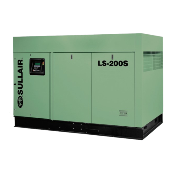
LS-200S
Operator's manual and parts list
Sullair LS-200S Operator's Manual And Parts List
Industrial air compressor
Hide thumbs
1
2
Table Of Contents
3
4
5
6
7
8
9
10
11
12
13
14
15
16
17
18
19
20
21
22
23
24
25
26
27
28
29
30
31
32
33
34
35
36
37
38
39
40
41
42
43
44
45
46
47
48
49
50
51
52
53
54
55
56
57
58
59
60
61
62
63
64
65
66
67
68
69
70
71
72
73
74
75
76
77
78
79
80
81
82
83
84
85
86
87
88
89
90
91
92
93
94
95
96
97
98
99
100
101
102
103
104
105
106
107
108
109
110
111
112
113
114
115
116
117
118
119
120
121
122
123
124
125
126
127
128
129
130
131
132
133
134
135
136
137
138
139
140
141
142
143
144
145
146
147
148
page
of
148
Go
/
148
Contents
Table of Contents
Troubleshooting
Bookmarks
Table of Contents
Table of Contents
General
Personal Protective Equipment
Pressure Release
Fire and Explosion
Hot Surfaces, Sharp Edges and Sharp Corners
Moving Parts
Toxic and Irritating Substances
Electrical Shock
Entrapment
Description of Components
Introduction
Sullair Compressor Unit, Functional Description
Compressor Cooling and Lubrication System, Functional Description
Compressor Discharge System, Functional Description
Control System, Functional Description
Air Inlet System, Functional Description
Table of Specifications
Lubrication Guide- Standard Compressors
Lubrication Guide- 24Kt Compressors
Lubrication Guide- Optional Fluid
Mounting of Compressor
Ventilation and Cooling
Service Air Piping
Coupling Alignment Check
Fluid Level Check
Motor Rotation Direction Check
Electrical Preparation
Purpose of Controls- Introduction
Purpose of Controls- Guide
Initial Start-Up Procedure
Subsequent Start-Up Procedure
Shutdown Procedure
General
Daily Operation
Maintenance after Initial 50 Hours of Operation
Maintenance Every 1000 Hours
Motor Bearings
Fluid Maintenance
Parts Replacement and Adjustment
Procedures
Air Filter Maintenance
Fluid Filter Maintenance
Separator Element Maintenance
Oil Return/Sight Glass Maintenance
Pressure Regulator Adjustment
Compressors with Optional Spiral Valve
Shaft Coupling Maintenance
Troubleshooting- Introduction
Troubleshooting Guide
Description of Components
Control System, Functional Description
Procedure for Ordering Parts
Recommended Spare Parts List
Motor, Compressor and Frame
Air Inlet System- Air-Cooled
Air Inlet System- Water-Cooled
Fluid Cooling System- Ls-200S & VCC-200S Air-Cooled
Fluid Cooling System- V-200S Air-Cooled
Fluid Cooling System- Water-Cooled
Air Piping System- Air-Cooled
Air Piping System- Water-Cooled
Fluid Piping System- Air-Cooled
Fluid Piping System- Water-Cooled
Moisture Drain- Air-Cooled
Sump and Parts
Pneumatic Controls- Ls-200S & VCC-200S
Pneumatic Controls- V-200S
Electrical Controls- Ls-200S & VCC-200S
Electrical Controls- V-200S
Electrical Controls- V-200S Externally Mounted
Enclosure- Air-Cooled
Enclosure- Water-Cooled
Decal Group
Decal Locations- Open Air-Cooled
Decal Locations- V-200S Open
Decal Locations- Open Water-Cooled
Decal Locations- V-200S Open Water-Cooled (380/575V+)
Decal Locations- Ls-200S Enclosed Air-Cooled
Decal Locations- V-200S & VCC-200S Enclosed Air-Cooled
Decal Locations- Ls-200S Enclosed Water-Cooled
Decal Locations- V-200S & VCC-200S Enclosed Water-Cooled
Decal Locations- Control Box Enclosure
Wiring Diagram- Ls-200S & Vcc200S with Supervisor Controller
Wiring Diagram- Ls-200S & Vcc200S Wye-Delta with Supervisor Controller
Wiring Diagram- Ls-200S & Vcc200S Full Voltage with Supervisor Controller
Wiring Diagram- V-200S with Supervisor Controller
Wiring Diagram- V-200S Ce with Supervisor Controller
Advertisement
Quick Links
1
Table of Contents
2
General
3
Troubleshooting Guide
Download this manual
INDUSTRIAL AIR
COMPRESSOR
L L S S -2 2 0 0 0 0 S S
V V C C C C -2 2 0 0 0 0 S S
125-150HP/ 90-110KW
STANDARD AND 24KT
2 2 0 0 0 0 S S
OPERATOR'S
MANUAL AND
PARTS LIST
KEEP FOR
FUTURE
REFERENCE
Part Number
02250145-909
©Sullair Corporation
Table of
Contents
Previous
Page
Next
Page
1
2
3
4
5
Advertisement
Table of Contents
Need help?
Do you have a question about the LS-200S and is the answer not in the manual?
Ask a question
Questions and answers
Related Manuals for Sullair LS-200S
Air Compressor Sullair LS-20S Operator's Manual And Parts List
Industrial air compressor (102 pages)
Air Compressor Sullair LS-20 Operator's Manual And Parts List
Industrial air compressor (114 pages)
Air Compressor Sullair LS20 Operator's Manual And Parts List
Industrial air compressor 100hp/ 75kw standard and 24kt including variable speed drive (156 pages)
Air Compressor Sullair LS-20T Operator's Manual
Industrial rotary screw air compressor air-cooled 350hp (36 pages)
Air Compressor Sullair LS20T Operator's Manual And Parts List
Industrial air compressor 200-300 hp / 150-224 kw supervisor controller (106 pages)
Air Compressor Sullair LS20T Operator's Manual And Parts List
Industrial air compressor 250-350hp/ 186-261kw 525 psig supervisor controller (96 pages)
Air Compressor Sullair LS20TS Operator's Manual And Parts List
Industrial air compressor (98 pages)
Air Compressor Sullair LS20TS Operator's Manual And Parts List
Industrial air compressor water-cooled: 300-600hp / 224-447kw air-cooled: 300-450hp / 224-336kw supervisor controller (146 pages)
Air Compressor Sullair LS-200 Operator's Manual And Parts List
Industrial air compressor 100hp/ 75kw air-cooled and water-cooeld standard and 24kt (166 pages)
Air Compressor Sullair LS20T 960 CFM Operator's Manual And Parts List
Industrial air compressor water-cooled: 300-600hp / 224-447kw air-cooled: 300-450hp / 224-336kw supervisor controller (146 pages)
Air Compressor Sullair LS20T 1100 CFM Operator's Manual And Parts List
Industrial air compressor water-cooled: 300-600hp / 224-447kw air-cooled: 300-450hp / 224-336kw supervisor controller (146 pages)
Air Compressor Sullair LS20T 1450 CFM Operator's Manual And Parts List
Industrial air compressor water-cooled: 300-600hp / 224-447kw air-cooled: 300-450hp / 224-336kw supervisor controller (146 pages)
Air Compressor Sullair LS25S-250 Operation & Maintenance Manual
Stationary screw compressor (54 pages)
Air Compressor Sullair LS25S-350 Operation & Maintenance Manual
Stationary screw compressor (54 pages)
Air Compressor Sullair LS-25 Operator's Manual And Parts List
Industrial air compressor 150-200hp/ 112-149kw air-cooled and water-cooled standard & 24kt (120 pages)
Air Compressor Sullair LS-25S Operator's Manual And Parts List
Industrial rotary screw air compressor (104 pages)
This manual is also suitable for:
V-200s
Vcc-200s
Table of Contents
Save PDF
Print
Rename the bookmark
Delete bookmark?
Delete from my manuals?
Login
Sign In
OR
Sign in with Facebook
Sign in with Google
Upload manual
Upload from disk
Upload from URL


Need help?
Do you have a question about the LS-200S and is the answer not in the manual?
Questions and answers