
Related Manuals for Sullair LS-20S


Summary of Contents for Sullair LS-20S
- Page 1 INDUSTRIAL AIR COMPRESSOR LS- -20S 125- -150HP/90- -110KW STANDARD AND 24KT OPERATOR’S MANUAL AND PARTS LIST KEEP FOR FUTURE REFERENCE Part Number 02250115-257 eSullair Corporation...
- Page 2 AIR CARE SEMINAR TRAINING Sullair Air Care Seminars are 3--day courses that provide hands--on instruction in the proper operation, maintenance and service of Sullair equipment. Individual seminars on Industrial compressors and compressor electrical systems are presented at regular intervals throughout the year at a dedicated training facility at Sullair’s corporate headquarters in Michigan City, Indiana.
-
Page 3: Table Of Contents
1.8 ELECTRICAL SHOCK 1.9 LIFTING 1.10 ENTRAPMENT Section 2 DESCRIPTION 2.1 INTRODUCTION 2.2 DESCRIPTION OF COMPONENTS 2.3 SULLAIR COMPRESSOR UNIT, FUNCTIONAL DESCRIPTION 2.4 COMPRESSOR COOLING AND LUBRICATION SYSTEM, FUNCTIONAL DESCRIPTION 2.5 COMPRESSOR DISCHARGE SYSTEM, FUNCTIONAL DESCRIPTION 2.6 CONTROL SYSTEM, FUNCTIONAL DESCRIPTION 2.7 AIR INLET SYSTEM, FUNCTIONAL DESCRIPTION... - Page 4 TABLE OF CONTENTS (CONTINUED) Section 5 PAGE OPERATION- 5.1 INTRODUCTION ELECTRO-MECHANICAL 5.2 PURPOSE OF CONTROLS 5.3 INITIAL START- -UP PROCEDURE 5.4 SUBSEQUENT START- -UP PROCEDURE 5.5 SHUTDOWN PROCEDURE Section 6 OPERATION- 6.1 BASIC INTRODUCTION SUPERVISOR II 6.2 KEYPAD 6.3 STATUS DISPLAYS 6.4 LAMP INDICATORS 6.5 SUPERVISOR II OPERATING PARAMETERS- SET-UP...
- Page 5 TABLE OF CONTENTS (CONTINUED) Section 8 ILLUSTRATIONS AND PARTS LIST (cont.) 8.3 MOTOR, COMPRESSOR AND FRAME 8.4 AIR INLET SYSTEM 8.5 COOLING AND LUBRICATION SYSTEM (AIR- -COOLED) 8.6 COOLING AND LUBRICATION SYSTEM (WATER-COOLED) 8.7 COOLER ASSEMBLY (AIR-COOLED) 8.8 COMPRESSOR DISCHARGE SYSTEM 8.9 AFTERCOOLER PIPING (AIR-COOLED- BEFORE JUNE 2000) 8.10 AFTERCOOLER PIPING (AIR-COOLED-...
- Page 6 NOTES...
-
Page 7: General
SAFETY 1.1 GENERAL of hose failure, per all applicable Federal, State and Sullair Corporation and its subsidiaries design and Local codes, standards and regulations. manufacture all of their products so they can be op- erated safely. However, the responsibility for safe B. -
Page 8: Fire And Explosion
Section 1 SAFETY 1.4 FIRE AND EXPLOSION K. DO NOT attempt to operate the compressor in any classification of hazardous environment unless the compressor has been specially designed and WARNING manufactured for that duty. 1.5 MOVING PARTS When installing a Base Load Transfer (BLT) Sys- A. -
Page 9: Electrical Shock
Section 1 SAFETY C. Operate the compressor only in open or ade- E. Disconnect, lock out, and tag all power at source quately ventilated areas. prior to attempting repairs or adjustments to rotating machinery and prior to handling any ungrounded D. -
Page 10: Entrapment
Section 1 SAFETY O. DO NOT use the lifting eye bolt on the compres- before doing so, or else secure and tag the access sor motor, if supplied, to lift the entire compressor door in the open position to avoid the possibility of package. -
Page 11: Description Of Components
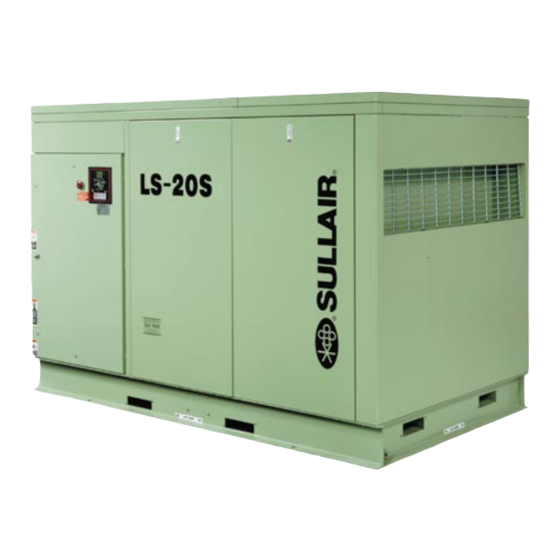
The inlet air filters are also mounted blies of the air compressors are clearly shown. The for easy access and servicing. Figure 2-1 Sullair Series LS-20S 150HP/ 110KW Rotary Screw Compressor (Air-cooled version) FLUID COOLER/ MINIMUM PRESSURE/ AFTERCOOLER... -
Page 12: Sullair Compressor Unit
With a Sullair compressor, there is no main- rotors and the compression chamber. tenance or inspection of the internal parts of the... - Page 13 Section 2 DESCRIPTION Figure 2-2 Compresor Piping and Instrumentation Diagram SEQUENCING LOAD CONTROL SOLENOID CHECK VALVE SOLENOID VALVE ORIFICE VALVE CONTROL FILTER INLET VALVE PRESSURE REGULATOR COMPRESSOR PRESSURE REGULATOR PRESSURE AIR FILTER FOR HIGH PRESSURE GAUGE SPIRAL MACHINES VALVE PRESSURE REGULATOR CLOSED INLET OPTION...
- Page 14 Section 2 DESCRIPTION Figure 2-3 Compressor Cooling and Lubrication System Diagram FLUID FLUID COOLER FILTER WATER-COOLED FLUID MACHINES STOP VALVE THERMAL VALVE FLUID FILTER FLUID STOP VALVE FLUID THERMAL COOLER VALVE AIR-COOLED MACHINES ments exceeds 10 psid (0.7 bar), the Supervisor II valve, located downstream from the separator, as- module displays a maintenance requirement mes- sures a minimum receiver pressure of 50 psig (3.5...
- Page 15 Section 2 DESCRIPTION Figure 2-4A Compressor Discharge System Diagram- Air-cooled Model MINIMUM PRESSURE/ AIR-COOLED CHECK VALVE MACHINES BEFORE JUNE 2000 BLOWDOWN VALVE SUMP TANK MOISTURE SEPARATOR FLUID LEVEL SIGHT GLASS FLUID FILL PLUG AFTERCOOLER MINIMUM PRESSURE/ CHECK VALVE BLOWDOWN VALVE MOISTURE SEPARATOR SUMP...
- Page 16 The functional description of the control system is described below All Sullair compressor models are equipped with a in four distinct phases of operation. For explanation high pressure shutdown protection to shut down the purposes, this description will apply to a compressor compressor at 20 psig (1.4 bar).
- Page 17 Section 2 DESCRIPTION Figure 2-5A Control System Diagram- Start and Full Load START BLOWDOWN VALVE SULLICON CONTROL INLET CONTROL CONTROL CYLINDER LINE FILTER PRESSURE SPIRAL GAUGE VALVE CHECK CHECK VALVE VALVE UNLOAD SOLENOID CLOSED INLET SOLENOID (OPTIONAL) SULLICON PRESSURE LIMITING REGULATOR SEQUENCING (HH &...
- Page 18 Section 2 DESCRIPTION Figure 2-5B Control System Diagram- Modulation and Unload BLOWDOWN MODULATION VALVE SULLICON CONTROL INLET CONTROL CONTROL CYLINDER LINE FILTER PRESSURE SPIRAL GAUGE VALVE CHECK CHECK VALVE VALVE UNLOAD SOLENOID CLOSED INLET SOLENOID (OPTIONAL) SULLICON PRESSURE LIMITING REGULATOR SEQUENCING (HH &...
- Page 19 Section 2 DESCRIPTION NORMAL OPERATING MODE - - 50 TO 100 PSIG Figure 2-6 Air Inlet System (3.5 TO 6.9 BAR) When the compressed air pressure rises above 50 AIR FILTER psig (3.5 bar), the minimum pressure valve opens and delivers compressed air to the service line. From this point on, the line air pressure is continually monitored by the Supervisor II.
- Page 20 Section 2 DESCRIPTION sor II energizes the solenoid valve allowing the air consists of a two- -stage, heavy- -duty, dry- -type pressure behind the Sullicon Control and the spiral filter with inertial dust separation and collection, a valve actuator to be vented through the solenoid butterfly- -type air inlet valve, and an adaptor valve exhaust port.
-
Page 21: Table Of Specifications
SORS once a year, whichever comes first. The fluid should be changed more frequently under severe operating Sullair standard compressors are filled with Sullube conditions, such as high ambient temperatures cou- fluid as factory fill. pled with high humidity, or when high particulate... - Page 22 Section 3 SPECIFICATIONS Sullair recommends that a 24KT sample be taken at WARNING the first filter change and sent to the factory for analysis. This is a free service. A sample kit with in- “The Plastic Pipe Institute recommends against the...
- Page 23 Section 3 SPECIFICATIONS Figure 3-1A Identification- Air-cooled Model (Prior to June 1, 2000)
- Page 24 Section 3 SPECIFICATIONS Figure 3-1B Identification- Air-cooled Model (After June 1, 2000)
- Page 25 Section 3 SPECIFICATIONS Figure 3-1C Identification- Water-cooled Model...
- Page 26 NOTES...
-
Page 27: Mounting Of Compressor Package
Consult a faces. Sullair representative for assistance in utilizing this heat. DANGER DO NOT install a water--cooled or an air--cooled/af- Do not twist frame. -
Page 28: Electrical Preparation
Parts Manual). plicable local electrical codes concerning isolation 3. Check all electrical connections for tightness. switches, fuse disconnects, etc. Sullair provides a 4. “DRY RUN” the electrical controls by disconnect- wiring diagram for use by the installer. -
Page 29: Purpose Of Controls
Section 5 COMPRESSOR OPERATION 5.1 INTRODUCTION tion, and use. While Sullair has built into the LS--20S Series pack- age a comprehensive array of controls and indica- 5.2 PURPOSE OF CONTROLS tors to assure its proper operation, the user should All Supervisor II Module (Supervisor) related func-... -
Page 30: Initial Start-Up Procedure
Section 6 COMPRESSOR OPERATION CONTROL OR INDICATOR PURPOSE BLOWDOWN VALVE ASSEMBLY Vents the sump vessel to atmosphere during unload- ing and shutdown. THERMAL MIXING VALVE Bypasses fluid flow around the cooler until the former reaches a temperature of 180_F (82_C). Useful for fast warm--up during start. - Page 31 NOTES...
- Page 32 AUTOMATIC MODE DISPLAY STOP BUTTON RUN LIGHT COMPRESSOR SYSTEM GRAPHIC COMPRESSOR RUN LIGHT POWER ON LIGHT CONTINUOUS START KEY PAD COMPRESSOR STOP/RESET KEY PAD DISPLAY PROGRAMMING AUTOMATIC MODE KEY SULLAIR LOGO KEY PAD MODE KEY PAD LCD SELECTION/PARAMETER VALUE CHANGE KEYPAD...
-
Page 33: Basic Introduction
Section 6 SUPERVISOR II 6.1 BASIC INTRODUCTION mode to increment a value. Refer to Figure 6--1. The Supervisor II has a two line display to show temperature, pressure and status. It has a keypad for operating the compressor, pro- gramming the control points and selecting displays. There is a graphic illustration with lamps that light to S Down arrow, lamp test -- Used in status show the item being displayed. -
Page 34: Lamp Indicators
Section 6 SUPERVISOR II If there are alarms active they will alternately be T2 210 shown with the default display. The machine status MAX 235 will be displayed for two seconds then the alarms for two seconds each. For example: S Total hours that the compressor has been running. -
Page 35: Supervisor Ii Operating Parameters
Section 6 SUPERVISOR II sump pressure rises above this pressure. presence of an alarm. MOTOR -- If flashing, indicates the motor overload P1 MAX contact has opened. 135 PSI INLET FILTER -- If flashing, indicates that inlet filter S Wye to delta transition timer --- For full maintenance is needed. -
Page 36: Operating The Compressor
Section 6 SUPERVISOR II S Communications Baud Rate --- This S Machine Capacity -- Used only for se- should always be selected to 9600 baud quencing, see Sequencing & Protocol for all sequencing modes. It may be lower Manual for details. for slave or monitoring modes. -
Page 37: Purpose Of Controls
Section 6 SUPERVISOR II P2 < LOAD - -- -> load solenoid turned on spond to start, stop, load or unload mes- sages. The remote inputs and outputs are POWER FAILURE RESTART enabled (start/stop, load/unload, master/lo- If the restart timer (RST TIME parameter) is dis- cal). -
Page 38: Daily Operation
Section 6 SUPERVISOR II 6.10 DAILY OPERATION tures, etc.). Following a routine start, observe the various Su- During the initial start--up or servicing of the pack- pervisor displays to check that normal readings are age, fluid may have to be added to the sump vessel being made -- previous records are very helpful in to restore an adequate level. -
Page 39: General
409264 should be performed when the Supervi- Your fluid filter includes a proprietary replaceable ele- sor displays AIR MNTN and the LED display flashes, ment available solely from Sullair and its agents -- DO or when corresponding maintenance message is dis- NOT substitute. -
Page 40: Separator Element Maintenance
Section 7 MAINTENANCE Figure 7-1 Air Filter (P/N 409264) BODY SECONDARY ELEMENT** WINGNUT WASHER RETAINING PLATE RETAINING CLAMP WASHER WASHER PRIMARY ELEMENT* WINGNUT WINGNUT COVER *Replacement Element (Primary) P/N 409853 **Replacement Element (Secondary) P/N 409854 3. Apply a light film of fresh oil to the new gasket and hand tighten new element until gasket contacts Figure 7-2 Compressor Fluid Filter the seat. -
Page 41: Sullicon Actuator Maintenance
Section 7 MAINTENANCE 2. Loosen/remove cap screw fastening the valve arm Figure 7-3 Separator Element Replacement link to the Sullicon control lever and let link hang aside. CAPSCREW 3. Loosen/remove the two (2) capscrew/nut assem- blies securing Sullicon to its mounting bracket and LOCK WASHER pull Sullicon away. - Page 42 -- if any faults are found, elements must be replaced and Please note that replacement of either shaft hub re- Sullair contacted for further assistance. quires the removal of the motor, an operation best 4. Reassemble in reverse order. Capscrews must be handled by Sullair personnel.
-
Page 43: Troubleshooting
Sullair repre- decrease of a dirty heat exchanger. sentative or the Sullair Corporation factory toll free at A detailed visual inspection is worth performing for 1--800--SULLAIR. - Page 44 Section 7 MAINTENANCE 7.7 TROUBLESHOOTING GUIDE (CONTINUED) SYMPTOM PROBABLE CAUSE REMEDY HI T1, HI T2 MESSAGE (cont.) Discharge Temperature Exceeded 235_F (113_C) Because: Fluid Level in Sump is Too Low Check/correct fluid level. Thermal Valve Malfunctioned Check/replace thermal valve. Cooler Fins are Dirty Clean cooler fins.
-
Page 45: Calibration
Section 7 MAINTENANCE 7.7 TROUBLESHOOTING GUIDE (CONTINUED) SYMPTOM PROBABLE CAUSE REMEDY P1 HI MESSAGE (continued) Pressure Regulator Maladjusted Check operation of pressure regulator. Solenoid Valve Failed Check operation of solenoid valve. to Operate Control Air Signal Leaks Check tubework feeding control signal for leaks. -
Page 46: Shutdown Settings
Section 7 MAINTENANCE crease or decrease always showing the total amount of adjustment. Maximum adjustment is + 7. The DSP key exits, wiping out changes to the current item, while saving changes to any previous items. The PRG key saves the current item and advances to the next. -
Page 47: Procedure For Ordering Parts
8.1 PROCEDURE FOR ORDERING PARTS Parts should be ordered from the nearest Sullair Representative or the Representative from whom the com- pressor was purchased. If for any reason parts cannot be obtained in this manner, contact the factory directly at the address or phone numbers below. -
Page 48: Motor, Compressor And Frame
Section 8 PARTS LIST 8.3 MOTOR, COMPRESSOR AND FRAME... - Page 49 (I) There is an exchange program whereby a remanufactured compressor unit can be obtained from Sullair distributors or the factory at less cost than the owner could repair the unit. For infor- mation regarding the unit exchange program, contact your nearest Sullair representative or the S ullair Cor por at ion.
-
Page 50: Air Inlet System
Section 8 PARTS LIST 8.4 AIR INLET SYSTEM WATER-COOLED MACHINES ONLY WATER-COOLED MACHINES ONLY... - Page 51 Section 8 PARTS LIST 8.4 AIR INLET SYSTEM part number description number quantity filter, air (I) 409264 nut, hex flanged 5/16”--18 825305--283 screw, hex ser washer 5/16” x 3/4” 829705--075 support, air filter (air-cooled only) 02250047--269 support, air filter (water-cooled only) 02250056--087 band, mounting 14”...
-
Page 52: Cooling And Lubrication System (Air- -Cooled)
Section 8 PARTS LIST 8.5 COOLING AND LUBRICATION SYSTEM (AIR- -COOLED) 15 16... - Page 53 Section 8 PARTS LIST 8. 5 CO O L I NG AND L UBRI CAT I O N SYST EM (AI R - - CO O L ED) part number description number quantity cooler, fluid 02250114--969 connector, tube 1 1/4” x 1 5/8” 811820--163 tube, by--pass to cooler 1 1/4”...
-
Page 54: Cooling And Lubrication System (Water-Cooled)
Section 8 PARTS LIST 8.6 COOLING AND LUBRICATION SYSTEM (WATER- -COOLED) 18 19... - Page 55 Section 8 PARTS LIST 8.6 COOLING AND LUBRICATION SYSTEM (WATER- -COOLED) part number description number quantity elbow, tube 1 1/4” x 1 5/8” 811620--162 cooler, fluid WC 02250114--977 bushing, reducing hex 1/2” x 1/4” 807602--010 tubing, steel 1/4” 841015--004 6 ft elbow, tube--M 1/4”...
-
Page 56: Cooler Assembly (Air-Cooled)
Section 8 PARTS LIST 8.7 COOLER ASSEMBLY (AIR- -COOLED) - Page 57 Section 8 PARTS LIST 8.7 COOLER ASSEMBLY (AIR- -COOLED) part number description number quantity cooler, fluid 02250114--969 insert, threaded blind 5/16”--18 02250043--765 adapter, venturi panel 02250043--027 panel, venturi 36” 245579 support, cooler 02250043--287 fan, 36” dia 405103 bushing, split taper 249853 support, cooler motor end 02250115--733...
-
Page 58: Compressor Discharge System
Section 8 PARTS LIST 8.8 COMPRESSOR DISCHARGE SYSTEM A- TO CONTROL LINE FILTER B- FROM LOAD CONTROL SOLENOID C- TO PRESSURE TRANSDUCER P1... - Page 59 Section 8 PARTS LIST 8.8 COMPRESSOR DISCHARGE SYSTEM part number description number quantity elbow, tube 1/4” x 1/4” 810504--025 tee, pipe 1/4” 868815--010 elbow, pipe--M to F 1/4” x 1/4” 860704--025 orifice 02250101--191 orifice 022033 glass, sight 1/4” 046559 nipple, pipe hex 1/4” x 1/4” 868504--025 strainer, v--type 1/4”...
- Page 60 Section 8 PARTS LIST 8.8 COMPRESSOR DISCHARGE SYSTEM A- TO CONTROL LINE FILTER B- FROM LOAD CONTROL SOLENOID C- TO PRESSURE TRANSDUCER P1...
- Page 61 Section 8 PARTS LIST 8.8 COMPRESSOR DISCHARGE SYSTEM (CONTINUED) part number description number quantity nut, hex 5/8”--11 825210--559 plug, o--ring boss 1 1/4” 040029 plug, sight glass 1 7/8” 02250097--611 bulkhead, pipe 1/2” 841500--008 connector, tube 1/2” x 1/2” 250024--695 t ube, t her m oplas t ic 1/ 2”...
-
Page 62: Aftercooler Piping (Air-Cooled
Section 8 PARTS LIST 8.9 AFTERCOOLER PIPING (AIR-COOLED- BEFORE JUNE 2000) - Page 63 Section 8 PARTS LIST 8.9 AFTERCOOLER PIPING (AIR-COOLED- BEFORE JUNE 2000) part number description number quantity bushing, reducing hex 1/2” x 1/4” 802102--010 tee, reducing 2” x 2” x 1/2” 802208--082 U--bolt, 3/8” x 2 1/2” 868306--250 support, moisture separator 02250115--692 nipple, pipe 2”...
- Page 64 Section 8 PARTS LIST 8.10 AFTERCOOLER PIPING (AIR-COOLED- AFTER JUNE 2000)
- Page 65 Section 8 PARTS LIST 8.10 AFTERCOOLER PIPING (AIR-COOLED- AFTER JUNE 2000) part number description number quantity bushing, reducing hex 1/2” x 1/4” 802102--010 tee, reducing 2” x 2” x 1/2” 802208--082 U--bolt, 3/8” x 2 1/2” 868306--250 support, moisture separator 02250119--770 nipple, pipe 2”...
-
Page 66: Aftercooler Piping (Water-Cooled)
Section 8 PARTS LIST 8.11 AFTERCOOLER PIPING (WATER-COOLED) - Page 67 Section 8 PARTS LIST 8.11 AFTERCOOLER PIPING (WATER-COOLED) part number description number quantity bushing, reducing hex 2” x 1 1/4” 802108--050 nipple, pipe 1 1/4” x 6” 822120--060 elbow, tube--M 1 1/4” x 1 1/4” 810520--125 elbow, pipe 1 1/4” 801515--050 connector, tube 1 1/4”...
-
Page 68: Unit Tubing
Section 8 PARTS LIST 8.12 UNIT TUBING... - Page 69 Section 8 PARTS LIST 8.12 UNIT TUBING part number description number quantity connector, tube--M 3/8” x 1/4” 810206--025 capscrew, ferry hd 1/2”--13 x 1” 867308--100 capscrew, hex GR8 5/16”--18 x 3/4” 828205--075 support, manifold 02250044--911 manifold, oil 1 5/8” SAE 02250115--094 orifice, .062”...
-
Page 70: Sullicon Control
Section 8 PARTS LIST 8.13 SULLICON CONTROL... - Page 71 Section 8 PARTS LIST 8.13 SULLICON CONTROL (I) part number description number quantity screw, machine hex 3/8”--16 x 2” 830106--200 nut, hex 3/8”--16 824206--337 bracket, control stop 020864 nut, hex 5/16”--18 824205--273 Snut, hex 3/8”--16 824206--337 washer, springlock 5/16” 837505--078 Swasher, springlock 3/8”...
-
Page 72: Pneumatic Controls Without Spiral Valve
Section 8 PARTS LIST 8.14 PNEUMATIC CONTROLS WITHOUT SPIRIAL VALVE A--TO BLOWDOWN VALVE B--TO SULLICON CONTROL C--TO TOP OF SEPARATOR TANK D--TO AFTERCOOLER (WATER) E--TO SIDE OF SEPARATOR TANK F--TO FLUID FILTER G--TO SERVICE AIR OUTLET H--TO AIR INLET ADAPTER 10 13 9 15... - Page 73 Section 8 PARTS LIST 8.14 PNEUMATIC CONTROLS WITHOUT SPIRIAL VALVE part number description number quantity plug, hole 1/2” 409918--002 RTD, 100 OHM 250039--909 locknut, conduit seal 1/2” 02250071--362 locknut, conduit 1/2” 847200--050 connector, tube--M 1/4” x 1/8” 810204--012 conduit 250007--170 elbow, 1/4”T x 1/4”P 250018--430 valve, solenoid 3--way 1/4”...
-
Page 74: Pneumatic Controls With Spiral Valve
Section 8 PARTS LIST 8.15 PNEUMATIC CONTROLS WITH SPIRIAL VALVE A--TO BLOWDOWN VALVE B--TO SULLICON CONTROL C--TO TOP OF SEPARATOR TANK D--TO INLET CONTROL CYLINDER E--TO SIDE OF SEPARATOR TANK F--TO FLUID FILTER G--TO SERVICE AIR OUTLET H--TO AIR INLET ADAPTER 9 10 6 12 7 TO UNIT... - Page 75 Section 8 PARTS LIST 8.15 PNEUMATIC CONTROLS WITH SPIRIAL VALVE part number description number quantity rtd, 100 ohm 250039--909 locknut, conduit seal 1/2” 02250071--362 conduit 250007--170 valve, solenoid 3--way 1/4” (I) 250038--675 elbow, 1/4”T x 1/4”P 250018--430 nipple, pipe 1/4” 868504--025 connector, tube--M 1/4”...
-
Page 76: Electrical Box
Section 8 PARTS LIST 8.16 ELECTRICAL BOX... - Page 77 Section 8 PARTS LIST 8.16 ELECTRICAL BOX part number description number quantity grip, cord 12/4 250018--495 wire, neoprene #12--4 850604--012 grip, cord 1/0 250014--561 wir e, t y pe G -- G C 2/ 0 250014 -- 311 7 f t s t ar t er, c om pr es s or c ons ult f ac t or y transformer, 350VA universal voltage...
-
Page 78: Enclosure (Air-Cooled)
Section 8 PARTS LIST 8.17 ENCLOSURE (AIR-COOLED) - Page 79 Section 8 PARTS LIST 8.17 ENCLOSURE (AIR-COOLED) part number description number quantity panel, canopy corner 02250116--305 support, bracket 02250078--690 panel, canopy corner 02250119--167 channel, support 02250116--312 panel, access 02250118--773 channel, support 02250116--311 latch, adjustable trigger 250007--835 panel, assembly 02250116--306 grille, air inlet compressor end 02250049--723 baffle, air inlet 02250046--858...
-
Page 80: Enclosure (Water-Cooled)
Section 8 PARTS LIST 8.18 ENCLOSURE (WATER-COOLED) - Page 81 Section 8 PARTS LIST 8.18 ENCLOSURE (WATER-COOLED) part number description number quantity panel, canopy corner 02250116--305 support, bracket 02250078--690 panel, canopy corner 02250119--167 channel, support 02250116--312 panel, access 02250118--773 channel, support 02250116--311 latch, adjustable trigger 250007--835 panel, assembly 02250116--306 grille, air inlet compressor end 02250049--723 baffle, air inlet 02250046--858...
-
Page 82: Acoustic Panels
Section 8 PARTS LIST 8.19 ACOUSTIC PANELS AIR-COOLED MACHINES WATER-COOLED MACHINES WATER-COOLED & AIR-COOLED MACHINES... - Page 83 Section 8 PARTS LIST 8.19 ACOUSTIC PANELS part number description number quantity panel, fiberglass (air-cooled only) 02250118--822 panel, fiberglass (air-cooled only) 02250118--824 panel, fiberglass (air-cooled only) 02250118--823 panel, fiberglass (water- & air-cooled) 02250118--826 panel, fiberglass (water- & air-cooled) 02250118--825 panel, fiberglass (water- & air-cooled) 02250118--827 panel, fiberglass (water- &...
-
Page 84: Decal Group
Section 8 PARTS LIST 8.20 DECAL GROUP ® ®... - Page 85 Section 8 PARTS LIST 8.20 DECAL GROUP part number description number quantity sign, warning sever -- fan 049855 sign, warning sever--fan port 049965 decal, rotation 250021--286 decal, rotation 250021--564 decal, voltage 460V/ 60Hz international 02250069--399 Sdecal, 380--415V/ 50Hz (not shown) 02250069-403 Sdecal, 525V/ 50Hz (not shown) 02250069-415...
- Page 86 Section 8 PARTS LIST 8.20 DECAL GROUP...
- Page 87 Section 8 PARTS LIST 8.20 DECAL GROUP (CONTINUED) part number description number quantity sign, warning ground fault 049852 decal, warning actuator 250029--836 decal, danger high voltage 042218 decal, water inlet--outlet 049873 decal, water in 250019--107 decal, water out 250019--108 decal, water drain 250022--810 decal, actuator valve positioning 250029--784...
- Page 88 Section 8 PARTS LIST 8.20 DECAL GROUP...
- Page 89 Section 8 PARTS LIST 8.20 DECAL GROUP (CONTINUED) part number description number quantity decal, ISO 9001 02250057--624 decal, fluid sample 250022--675 sign, warning “food grade” lube 250003--144 sign, warning “compressor fluid fill cap” 049685 decal, warning auto start 250017--903 (Continued on page 85) PLEASE NOTE: WHEN ORDERING PARTS, INDICATE SERIAL NUMBER OF COMPRESSOR...
- Page 90 Section 8 PARTS LIST 8.20 DECAL GROUP...
- Page 91 8.20 DECAL GROUP (CONTINUED) part number description number quantity decal, electrical component ID 02250109--734 decal, LS--20S (open) 02250061--058 Sdecal, LS--20S (canopy) 02250061--161 decal, Sullair logo (open) 02250059-058 Sdecal, Sullair logo (canopy) 02250057--603 PLEASE NOTE: WHEN ORDERING PARTS, INDICATE SERIAL NUMBER OF COMPRESSOR...
-
Page 92: Decal Locations
Section 8 PARTS LIST 8.21 DECAL LOCATIONS... - Page 93 LS--20S (open) 02250061--058 decal, warning auto start 250017--903 sign, warning sever -- fan 049855 decal, ISO 9001 02250057--624 decal, Sullair logo (open) 02250059-058 decal, fork lifting 241814 decal, warning mixing fluids 02250110--891 decal, fluid Sullube 02250069--389 Sdecal, fluid 24 KT...
- Page 94 Section 8 PARTS LIST 8.21 DECAL LOCATIONS WATER-COOLED MODEL...
- Page 95 -- fan 049855 sign, danger electrocution 049850 decal, ISO 9001 02250057--624 decal, fork lifting 241814 decal, fluid 24 KT (I) 02250069--395 decal, Sullair logo (canopy) 02250057--603 decal, LS--20S (canopy) 02250061--161 decal, autostart 041065 decal, water out 250019--108 decal, water in 250019--107 (I) Decal no.
- Page 96 Section 8 PARTS LIST 8.21 DECAL LOCATIONS...
- Page 97 Section 8 PARTS LIST 8.21 DECAL LOCATIONS part number description number quantity decal, earth ground international 02250075--046 decal, PE designation international 0225075--540 decal, danger high voltage 042218 decal, voltage 460V/ 60Hz international 02250069--399 Sdecal, 380--415/50Hz (not shown) 02250069-403 Sdecal, 525V/ 50Hz (not shown) 02250069-415 Sdecal, 575V/ 60Hz (not shown) 02250069-400...
-
Page 98: Wiring Diagram- Standard Full Voltage Supervisor Ii Deluxe
Section 8 PARTS LIST 8.22 WIRING DIAGRAM- STANDARD FULL VOLTAGE SUPERVISOR II DELUXE... -
Page 99: Wiring Diagram- Standard Wye-Delta
Section 8 PARTS LIST 8.23 WIRING DIAGRAM- STANDARD WYE-DELTA SUPERVISOR II DELUXE... - Page 100 Section 8 PARTS LIST 8.24 WIRING DIAGRAM- STANDARD WYE-DELTA SUPERVISOR II DELUXE (EUROPE)
- Page 101 NOTES...
- Page 102 WORLDWIDE SALES AND SERVICE SULLAIR ASIA, LTD. SULLAIR EUROPE, S.A. Sullair Road, No. 1 Zone Des Granges BP 82 Chiwan, Shekou 42602 Montbrison Cedex, France Shenzhen, Guangdong PRV. Telephone: 33- -477968470 PRC POST CODE 518068 Fax: 33- -477968499 Telephone: 755- -6851686...
Need help?
Do you have a question about the LS-20S and is the answer not in the manual?
Questions and answers