Sullair LS-20T Operator's Manual
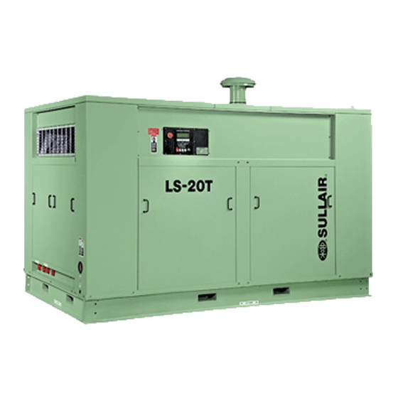
Industrial rotary screw air compressor air-cooled 350hp
Hide thumbs
Also See for LS-20T:
- Operator's manual and parts list (106 pages) ,
- Operator's manual and parts list (96 pages)

Related Manuals for Sullair LS-20T


Summary of Contents for Sullair LS-20T
- Page 1 INDUSTRIAL ROTARY SCREW AIR COMPRESSOR LS---20T AIR---COOLED 350HP OPERATOR’S MANUAL Part Number 02250128---044 eSullair Corporation...
- Page 2 AIR CARE SEMINAR TRAINING Sullair Air Care Seminars are 3--day courses that provide hands--on instruction in the proper operation, maintenance and service of Sullair equipment. Individual seminars on Industrial compressors and compressor electrical systems are presented at regular intervals throughout the year at a dedicated training facility at Sullair’s corporate headquarters in Michigan City, Indiana.
-
Page 3: Table Of Contents
1.8 ELECTRICAL SHOCK 1.9 LIFTING 1.10 ENTRAPMENT Section 2 DESCRIPTION 2.1 INTRODUCTION 2.2 DESCRIPTION OF COMPONENTS 2.3 SULLAIR COMPRESSOR UNIT, FUNCTIONAL DESCRIPTION 2.4 COMPRESSOR COOLING AND LUBRICATION SYSTEM, FUNCTIONAL DESCRIPTION 2.5 COMPRESSOR DISCHARGE SYSTEM, FUNCTIONAL DESCRIPTION 2.6 CONTROL SYSTEM, FUNCTIONAL DESCRIPTION 2.7 AIR INLET SYSTEM, FUNCTIONAL DESCRIPTION... - Page 4 TABLE OF CONTENTS (CONTINUED) Section 5 PAGE OPERATION 5.1 GENERAL 5.2 PURPOSE OF CONTROLS 5.3 INITIAL START---UP PROCEDURE 5.4 SUBSEQUENT START---UP PROCEDURE 5.5 SHUTDOWN PROCEDURE Section 6 SUPERVISOR II DESCRIPTION 6.1 BASIC INTRODUCTION 6.2 KEYPAD --- ALL MODELS 6.3 STATUS DISPLAYS 6.4 LAMP INDICATORS 6.5 PARAMETER SETUP 6.6 OPERATING THE COMPRESSOR...
-
Page 5: General
Section 1 SAFETY 1.1 GENERAL pressure in case of hose failure, per all applicable Sullair Corporation and its subsidiaries design and Federal, State and Local codes, standards and manufacture all of their products so they can be op- regulations. erated safely. However, the responsibility for safe B. -
Page 6: Fire And Explosion
Section 1 SAFETY 1.4 FIRE AND EXPLOSION K. DO NOT attempt to operate the compressor in any classification of hazardous environment unless the compressor has been specially designed and WA R N I N G manufactured for that duty. When installing a Base Load Transfer (BLT) Sys- 1.5 MOVING PARTS tem, remove jumpers between 16---17 &... -
Page 7: Electrical Shock
Section 1 SAFETY C. Operate the compressor only in open or ade- E. Disconnect, lock out, and tag all power at source quately ventilated areas. prior to attempting repairs or adjustments to rotat- ing machinery and prior to handling any un- D. -
Page 8: Entrapment
Section 1 SAFETY cause the compressor to tumble off, possibly caus- form service adjustments, inform other personnel ing serious injury or property damage in the pro- before doing so, or else secure and tag the access cess. door in the open position to avoid the possibility of others closing and possibly latching the door with O. -
Page 9: Introduction
With a Sullair compressor, there is no inspec- the compression heat from the cooling fluid. tion required of the working parts within the com- Provisions are made for easy access to such com- pressor unit. -
Page 10: Compressor Cooling And Lubrication System, Functional Description
TIONAL DESCRIPTION which senses the temperature of the fluid and di- rects the flow accordingly. While the temperature The Sullair compressor unit discharges the com- of the fluid is below the thermostat temperature pressed air/fluid mixture through a discharge range, the fluid is routed directly back toward the check valve into the combination receiver/sump. - Page 11 Section 2 DESCRIPTION Figure 2 ---2A Piping and Instrumentation 02250125---659R3...
- Page 12 Section 2 DESCRIPTION Figure 2 ---2B Piping And Instrumentation Key 02250125---659R3...
-
Page 13: Control System, Functional Description
265_F (130_C) on second stage. is energized allowing air into the poppet valve and into the compressor inlet. As discharge pressure All Sullair compressor models are equipped with a start to build, the reference pressure regulator high pressure shutdown switch to shut down the opens and maintains a maximum of 60psi (414kPa) compressor at 365 psig (2515kPa). -
Page 14: Air Inlet System, Functional Description
Section 2 DESCRIPTION MODULATING MODE – 340 TO 360PSI (2344 TO pet valve, which is to atmosphere through the air in- 2482KPA) let filter. If less than the rated capacity of compressed air is 2.7 AIR INLET SYSTEM, FUNCTIONAL DESCRIP- being utilized, the service line pressure will rise TION above the 340psi (2344kPa). -
Page 15: Specifications
Operator’s manual. “The Plastic Pipe Institute recommends against the use of thermoplastic pipe to transport com- Sullair encourages the user to participate in a fluid pressed air or other compressed gases in exposed analysis program with the fluid suppliers. This could above ground locations, e.g. - Page 16 NOTES...
-
Page 17: Mounting Of Compressor
OSHA, National Electrical Code, and any other throughout the system. applicable local electrical code concerning isola- tion switches, fused disconnects, etc. Sullair pro- vides a wiring diagram for use by the installer. NOTE A few electrical checks should be made to help as- Under certain conditions for inside installations, sure that the first start---up will be trouble free. - Page 18 NOTES...
-
Page 19: General
OPERATION 5.1 GENERAL for service or indicate the beginning of a malfunc- While Sullair has built into this compressor a com- tion. Before starting your Sullair compressor, read prehensive array of controls and indicators to as- this section thoroughly and familiarize yourself with... -
Page 20: Initial Start
Section 5 OPERATION 5.2 PURPOSE OF CONTROLS CONTROL OR INDICATOR PURPOSE PRESSURE SWITCH Senses service line pressure. When line pressure reaches maximum operating pressure, the pressure switch signals the blowdown valve to unload the com- pressor. MINIMUM PRESSURE/CHECK VALVE Maintains a minimum pressure of 160 psig (1103kPa) in the sump. - Page 21 NOTES...
- Page 22 Section 6 SUPERVISOR II DESCRIPTION Figure 6-1 Supervisor II Panel...
-
Page 23: Basic Introduction
Section 6 SUPERVISOR II DESCRIPTION 6.1 BASIC INTRODUCTION Refer to Figure 6---1. The Supervisor II has a two line display to show temperature, pressure and sta- tus. It has a keypad for operating the compressor, displays to change displays and in param- programming the control points and selecting dis- eter setup mode to increment a value. -
Page 24: Lamp Indicators
Section 6 SUPERVISOR II DESCRIPTION other status information. To scroll through the dis- T4 HI shutdown will occur. plays press the up arrow or down arrow keys. Up arrow moves to the next display, down arrow the T4 210 previous display. To return to the default display MAX 235 press the display key. -
Page 25: Parameter Setup
Section 6 SUPERVISOR II DESCRIPTION T3 --- (Oil temperature) If lit steady, signifies that T3 sump pressure rises above this pressure. is being displayed, if flashing denotes the presence of an alarm. P1 MAX 135 PSI T4 --- (Interstage temperature) If lit steady, signifies that T4 is being displayed, if flashing denotes the S Wye to delta transition timer --- For full presence of an alarm. -
Page 26: Operating The Compressor
Section 6 SUPERVISOR II DESCRIPTION for slave or monitoring modes. S Sequence Hours --- Used only for se- quencing, see Sequencing & Protocol Manual for details. BAUDRATE 9600 SEQ HRS S Sequence method --- This parameter sets 1000 the method used for sequencing. The choices are DISABLED, REMOTE, SLAVE, HOURS, COM ID#. -
Page 27: Purpose Of Controls
Section 6 SUPERVISOR II DESCRIPTION POWER FAILURE RESTART rameter change messages but will not re- If the restart timer (RST TIME parameter) is dis- spond to start, stop, load or unload mes- abled the compressor will not try to start after a sages. -
Page 28: Daily Operation
6.11 TROUBLESHOOTING INTRODUCTION Should your problem persist after making the rec- The following information has been compiled from ommended check, consult your nearest Sullair operational experience with your package. It identi- representative or the Sullair Corporation. 6.12 TROUBLESHOOTING GUIDE... -
Page 29: Calibration
Section 6 SUPERVISOR II DESCRIPTION 6.12 TROUBLESHOOTING GUIDE (CONTINUED) SYMPTOM PROBABLE CAUSE REMEDY SEP MNTN Message Plugged separator Replace separator elements. ∆P1 > 10 PSI (0.7 bar) Check P1 & P2 pressure transducers. COMPRESSOR DOES NOT BUILD FULL DISCHARGE PRESSURE Air Demand Exceeds Supply Check air service lines for open valves or leaks. - Page 30 NOTES...
-
Page 31: General
NOTE ized. Stop compressor and relieve all internal pressure To assist with the removal of the tank lid, Sullair before doing so. has provided a 1”---8 nut to the top lid so it can be removed by a 1”---8 eye bolt (which is available 7.2 DAILY OPERATION... -
Page 32: Servicing The Fluid Filter
Section 7 MAINTENANCE Figure 7 ---2 Full Flow Fluid Filter (P/N 02250111 ---592) FILTER RESTRICTION INDICATOR FILTER HEAD BOWL SEAL (O--RING)* ELEMENT* BOWL DRAIN PLUG * Element Repair Kit P/N 250031---850 Silglyde). Now install the new separator ele- 6. Check bowl o---ring for damage and replace if ments and retaining ring. -
Page 33: Troubleshooting
9. With the secondary element in place, clean or re- Should your problem persist after making the rec- place the primary element. Cleaning instructions ommended check, consult your nearest Sullair rep- follow. resentative or the Sullair Corporation factory. - Page 34 NOTES...
-
Page 35: Procedure For Ordering Parts
SPARE PARTS LIST 8.1 PROCEDURE FOR ORDERING PARTS Parts should be ordered from the nearest Sullair Representative or the Representative from whom the com- pressor was purchased. If for any reason parts cannot be obtained in this manner, contact the factory directly at the address below. - Page 36 WORLDWIDE SALES AND SERVICE SULLAIR ASIA, LTD. SULLAIR EUROPE, S.A. Sullair Road, No. 1 Zone Des Granges BP 82 Chiwan, Shekou 42602 Montbrison Cedex, France Shenzhen, Guangdong PRV. Telephone: 33- -477968470 PRC POST CODE 518068 Fax: 33- -477968499 Telephone: 755- -6851686...
Need help?
Do you have a question about the LS-20T and is the answer not in the manual?
Questions and answers